In my previous post, I mentioned that Cisco ASA remote access can be easily setup using VPN wizard. One of the steps involve creating a IP address pool or DHCP server to assign dynamically inside IP addresses to the remote clients. Often, this range of IP addresses may not be routable in the trusted networks.
To resolve it, you either use NAT or Reverse Route Injection (RRI). For the latter, a static host route for the remote client would be injected into the IGP (e.g. RIP or OSPF), so that it would become routable. Enabling RRI is easy, on the ASDM conole, click on "Remote Access VPN > Network Access > Advanced > IPSec -> Crypto Maps". Edit an existing map, click on "Tunnel Policy (Crypto Map) - Advanced" tab and check on "Enable Reverse Route Injection".
Alternatively, on the command line, just append set reverse-route on the existing crypto map, e.g. "crypto dynamic-map SYSTEM_DEFAULT_CRYPTO_MAP 65535 set reverse-route".
I have a wide scope of interests in IT, which includes hyper-v private cloud, remote desktop services, server clustering, PKI, network security, routing & switching, enterprise network management, MPLS VPN on enterprise network etc. Started this blog for my quick reference and to share technical knowledge with our team members.
Showing posts with label cisco vpn. Show all posts
Saturday, April 9, 2011
Thursday, April 7, 2011
Cisco ASA Remote Access with external PKI
It's trivial to setup Cisco ASA remote access by just running the "Remote Access" wizards. However, if you are relying on external PKI (e.g. Microsoft CA or OpenSSL) for certificate-based authentication, it can be a headache to troubleshoot. To minimize such hassles, try to import the CA cert and settle the VPN key-pairs before running the wizard. As for VPN certificate, I would recommend generating the cert request from Cisco ASDM console (i.e. self-enrollment) rather than importing, as the imported certificate may not contain the right constraints.
To import the CA certificate, click on "Configuration > Remote Access VPN > Certificate Management > CA certificates > Add". To generate the new key-pair for the ASA, click one tab below on Identity Certificates and a dialog box would appear:
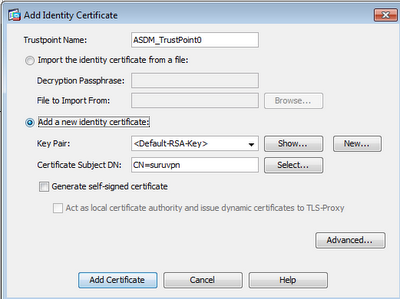
Click on "New..." button, give it a new name and generate the new key-pair. Click on "Add Certificate" button and generate a p10 certificate request. Copy out the cert request file and send it over to the CA for issuance. In any case that you have to modify the X.509 attributes (e.g. CN, email etc), you don't have to re-generate a new key. Just delete away the old cert and re-use the same key for another new cert request. Run the step-by-step Remote Access Wizard.
However, the wizard won't set the default IKE profile to cert authentication. On "Advanced > IPSec > IKE Policies", create a highest priority (i.e. smallest number) on the IKE policies with authentication to "rsa-sig" or "authentication rsa-sig" under "crypto isakmp policy 1" on global config to ensure certificate authentication during the IKE phase. By default, the authentication would also be mapped to the default "DefaultRAGroup" instead of the newly generated profile. Click on "Advanced > IPSec > Certificate to Connection Profile Maps". This is to map the certificates to the right IPSec profile during the initial IKE authentication. Click on the "Add" button, create a new connection and map to your earlier wizard generated IPSec profile. Then click on the "Add button" below the Mapping Criteria for cert attribute matching.
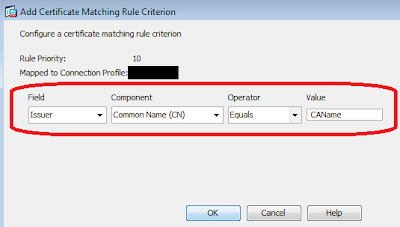
As all certificates in the chain have the same issuer, my preference is to match the Common Name (CN) of the issuing CA.
On the front-end Cisco VPN client, you may choose any methods to enrol the client smart card or just by importing the p12 soft-tokens into the default Cisco store. Nothing much else is needed to configure on the front-end, except setting the destination host to the outside interface of your Cisco ASA VPN. Hopefully, there should be no errors. If there is, I find it easier to troubleshoot on the front-end client (rather than debugging on the back-end console) by enabling logging (Ctrl-E) and Ctrl-L to show the Log Window. Tweak the logging levels on the "Log Setting". The most common log sources would be the Certificates and IKE. If you wish, you may also turn on debugging on the backend using "debug crypto ca 127" and "debug crypto isakmp 127". Earlier, I saw a debug error on VPN client saying: Unable to establish Phase 1 SA with server because of "DEL_REASON_IKE_NEG_FAILED". Set the IKE authentication to auto by entering "isakmp identity auto" on the global config.
To import the CA certificate, click on "Configuration > Remote Access VPN > Certificate Management > CA certificates > Add". To generate the new key-pair for the ASA, click one tab below on Identity Certificates and a dialog box would appear:
Click on "New..." button, give it a new name and generate the new key-pair. Click on "Add Certificate" button and generate a p10 certificate request. Copy out the cert request file and send it over to the CA for issuance. In any case that you have to modify the X.509 attributes (e.g. CN, email etc), you don't have to re-generate a new key. Just delete away the old cert and re-use the same key for another new cert request. Run the step-by-step Remote Access Wizard.However, the wizard won't set the default IKE profile to cert authentication. On "Advanced > IPSec > IKE Policies", create a highest priority (i.e. smallest number) on the IKE policies with authentication to "rsa-sig" or "authentication rsa-sig" under "crypto isakmp policy 1" on global config to ensure certificate authentication during the IKE phase. By default, the authentication would also be mapped to the default "DefaultRAGroup" instead of the newly generated profile. Click on "Advanced > IPSec > Certificate to Connection Profile Maps". This is to map the certificates to the right IPSec profile during the initial IKE authentication. Click on the "Add" button, create a new connection and map to your earlier wizard generated IPSec profile. Then click on the "Add button" below the Mapping Criteria for cert attribute matching.
As all certificates in the chain have the same issuer, my preference is to match the Common Name (CN) of the issuing CA.On the front-end Cisco VPN client, you may choose any methods to enrol the client smart card or just by importing the p12 soft-tokens into the default Cisco store. Nothing much else is needed to configure on the front-end, except setting the destination host to the outside interface of your Cisco ASA VPN. Hopefully, there should be no errors. If there is, I find it easier to troubleshoot on the front-end client (rather than debugging on the back-end console) by enabling logging (Ctrl-E) and Ctrl-L to show the Log Window. Tweak the logging levels on the "Log Setting". The most common log sources would be the Certificates and IKE. If you wish, you may also turn on debugging on the backend using "debug crypto ca 127" and "debug crypto isakmp 127". Earlier, I saw a debug error on VPN client saying: Unable to establish Phase 1 SA with server because of "DEL_REASON_IKE_NEG_FAILED". Set the IKE authentication to auto by entering "isakmp identity auto" on the global config.
Tuesday, April 5, 2011
VRF-aware Dynamic Multipoint VPN
Following on my previous post on VRF-aware Multipoint GRE, you can further protect the mGRE tunnels with IPSec easily.
To verify, perform the following commands and check the status in bold:
- On all Routers
- !
- crypto keyring ciscokey vrf outer
- pre-shared-key address 172.16.0.0 255.255.0.0 key cisco123
- !
- crypto isakmp profile isaDMVPN
- keyring ciscokey
- match identity address 172.16.0.0 255.255.0.0 outer
- !
- crypto ipsec transform-set tfDMVPN esp-aes esp-sha-hmac
- mode transport
- !
- crypto ipsec profile proDMVPN
- set security-association lifetime seconds 900
- set transform-set tfDMVPN set isakmp-profile isaDMVPN
- !
- interface Tunnel1
- ip vrf forwarding inner
- tunnel protection ipsec profile proDMVPN #apply protection on tunnel
To verify, perform the following commands and check the status in bold:
- Router1#sh crypto isakmp sa
- IPv4 Crypto ISAKMP SA
- dst src state conn-id slot status
- 172.16.1.1 172.16.1.2 QM_IDLE 1001 0 ACTIVE
- ......
- Router1#sh crypto session
- Crypto session current status
- Interface: Tunnel1
- Profile: isaDMVPN
- Session status: UP-ACTIVE
- ......
If you couldn't obtain the above results, perform further troubleshooting using "debug crypto isakmp" and "debug crypto ipsec". Most of the time, the issues are related to isakmp issues and authentication key. Check that all the parameters (esp pre-shared key) can match.
Labels:
cisco networking,
cisco vpn
Monday, April 4, 2011
VRF-aware Multipoint GRE Tunnel
GRE tunnel is especially useful to encapsulate network traffic (including IGP routing) separate from the underlying infrastructure. One useful way is to create a logical Out-of-Band (OOB) management interface for network management on another VRF. The default point-to-point GRE tunnels are easy to setup when you have few remote sites to connect to. It will become less scalable, as the number of sites grow. To overcome it, consider point-to-multipoint tunnel instead. Instead of having multiple tunnels on the Hub router, you can have just one tunnel to connect to all spoke sites. And you don't have to manually map all the spoke destination addresses, as all the spoke routers will register dynamically with the Hub router. Consider the following diagram (click to enlarge):
Assuming that the outer VRF (including the loopback interfaces) is already made routable (e.g. OSPF, BGP etc) within this network. We are setting up another VRF on the inner for network management purposes.
If you have a second Hub router on the headend, you can setup another multippoint tunnel for redundancy like the following diagram:
Nevertheless, the newly created overlay VPN remains in plain. You may also wish to protect it using IPSec. Cisco calls this combination of IPSec and Multipoint GRE as "Dynamic Multipoint VPN" or "DMVPN", which I should blog about it in my next post.
Assuming that the outer VRF (including the loopback interfaces) is already made routable (e.g. OSPF, BGP etc) within this network. We are setting up another VRF on the inner for network management purposes. - On Hub CE Router A:
- interface Tunnel1
- ip vrf forwarding inner
- ip address 192.168.1.1 255.255.255.0
- ip nhrp authentication cisco #ensure matching key for all spokes
- ip nhrp map multicast dynamic
- ip nhrp network-id 123 #also ensure network-id can match
- ip ospf network broadcast
- ip ospf priority 10
- tunnel source Loopback0 #note that the destination is not defined
- tunnel mode gre multipoint
- tunnel key 123 # and the tunnel key as well
- tunnel vrf outer # create a tunnel on the outer vrf
- !
- router ospf 120 vrf inner
- network 172.16.1.1 0.0.0.0 area 0
- network 192.168.1.0 0.0.0.255 area 0
- On spoke router B
- interface Tunnel1
- ip vrf forwarding inner
- ip address 192.168.1.2 255.255.255.0
- ip nhrp authentication cisco
- ip nhrp map 192.168.1.1 10.1.1.1 #map inner vrf to outer vrf on hub router
- ip nhrp map multicast 10.1.1.1 #register with nhrp hub using multicast
- ip nhrp network-id 123
- ip nhrp nhs 192.168.1.1 #define hub router as next hop
- ip ospf network broadcast
- ip ospf priority 0
- tunnel source Loopback0
- tunnel mode gre multipoint
- tunnel key 123
- tunnel vrf outer
- !
- router ospf 120 vrf inner
- network 172.16.1.2 0.0.0.0 area 0
- network 192.168.1.0 0.0.0.255 area 0
- On spoke router C
- interface Tunnel1
- ip vrf forwarding inner
- ip address 192.168.1.3 255.255.255.0
- ip nhrp authentication cisco
- ip nhrp map 192.168.1.1 10.1.1.1 #map inner vrf to outer vrf on hub router
- ip nhrp map multicast 10.1.1.1 #register with nhrp hub using multicast
- ip nhrp network-id 123
- ip nhrp nhs 192.168.1.1 #define hub router as next hop
- ip ospf network broadcast
- ip ospf priority 0
- tunnel source Loopback0
- tunnel mode gre multipoint
- tunnel key 123
- tunnel vrf outer
- !
- router ospf 120 vrf inner
- network 172.16.1.3 0.0.0.0 area 0
- network 192.168.1.0 0.0.0.255 area 0
If you have a second Hub router on the headend, you can setup another multippoint tunnel for redundancy like the following diagram:
Nevertheless, the newly created overlay VPN remains in plain. You may also wish to protect it using IPSec. Cisco calls this combination of IPSec and Multipoint GRE as "Dynamic Multipoint VPN" or "DMVPN", which I should blog about it in my next post.
Labels:
cisco networking,
cisco vpn
Thursday, November 26, 2009
VRF aware Site-to-Site IPSec
Cisco introduced new configuration guidelines for VRF aware IPSec. I spent a day worth and finally got it working. The understanding of Front Door VRF (FVRF) and and Inside VRF (IVRF) is key. Each IPsec tunnel is associated with two VRF domains. The outer encapsulated packet belongs to one VRF domain, which Cisco called it FVRF. The inner & encrypted IP packet belongs to another domain called the IVRF.
Part 1 is the base configuration without any IPSec. I'm using Loopback interface to simulate internal trusted network address (e.g. LAN). GRE tunnel is setup to bridge 2 separate LANs. In part 2, IPSec profile is applied to encrypt GRE tunnel (a.k.a GRE over IPSec).
Part 1 - Base Configuration
hostname Router1
ip vrf FVRF
rd 0:0
!
ip vrf IVRF
rd 1:1
!
interface Loopback0 # internal address
ip vrf forwarding IVRF
ip address 192.168.255.1 255.255.255.255
!
interface Tunnel0
ip vrf forwarding IVRF
ip add 192.168.1.1 255.255.255.252
tunnel source Serial1/0
tunnel destination 192.168.1.2
tunnel vrf FVRF
!
interface Serial1/0
ip vrf forwarding FVRF
ip address 192.168.1.1 255.255.255.252
!
ip route vrf IVRF 192.168.255.2 255.255.255.255 Tunnel0
----
hostname Router2
ip vrf FVRF
rd 0:0
!
ip vrf IVRF
rd 1:1
!
interface Loopback0
ip vrf forwarding IVRF
ip address 192.168.255.2 255.255.255.255
!
interface Tunnel0
ip vrf forwarding IVRF
ip add 192.168.1.2 255.255.255.252
tunnel source Serial1/0
tunnel destination 192.168.1.1
tunnel vrf FVRF
!
interface Serial1/0
ip vrf forwarding FVRF
ip address 192.168.1.2 255.255.255.252
!
ip route vrf IVRF 192.168.255.1 255.255.255.255 Tunnel0
Part 2 - IPSec related crypto configuration
Router1
crypto keyring vpnKey vrf FVRF
pre-shared-key add 192.168.1.2 key vpnkey
no crypto xauth s1/0 #exempt extended authentication for physical interface
!
crypto isakmp policy 1
authentication pre-share
!
crypto isakmp profile isaPro
vrf FVRF
keyring vpnKey
match identity add 192.168.1.2 255.255.255.255 FVRF
!
crypto ipsec transform-set myset esp-des esp-md5-hmac
!
crypto ipsec profile ipsecPro
set transform myset
set isakmp-profile isaPro
!
int Tunnel0
tunnel mode ipsec ipv4 #apply IPSec to protect GRE tunnel
tunnel protection ipsec profile ipsecPro
!
-------
Router2
crypto keyring vpnKey vrf FVRF
pre-shared-key add 192.168.1.1 key vpnkey
!
no crypto xauth s1/0
!
crypto isakmp policy 1
authentication pre-share
!
crypto isakmp profile isaPro
vrf FVRF
keyring vpnKey
match identity add 192.168.1.1 255.255.255.255 FVRF
!
crypto ipsec transform-set myset esp-des esp-md5-hmac
!
crypto ipsec profile ipsecPro
set transform myset
set isakmp-profile isaPro
!
int Tunnel0
tunnel mode ipsec ipv4
tunnel protection ipsec profile ipsecPro
Verification
Router1#ping vrf IVRF 192.168.255.2 source lo0
Type escape sequence to abort.
Sending 5, 100-byte ICMP Echos to 192.168.255.2, timeout is 2 seconds:
Packet sent with a source address of 192.168.255.1
!!!!!
Success rate is 100 percent (5/5), round-trip min/avg/max = 372/429/512 ms
Router1#sh crypto isakmp sa
IPv4 Crypto ISAKMP SA
dst src state conn-id slot status
192.168.1.1 192.168.1.2 QM_IDLE 1001 0 ACTIVE
IPv6 Crypto ISAKMP SA
Router1#sh crypto session
Crypto session current status
Interface: Tunnel0
Profile: isaPro
Session status: UP-ACTIVE
Peer: 192.168.1.2 port 500
IKE SA: local 192.168.1.1/500 remote 192.168.1.2/500 Active
IPSEC FLOW: permit ip 0.0.0.0/0.0.0.0 0.0.0.0/0.0.0.0
Active SAs: 2, origin: crypto map
Part 1 is the base configuration without any IPSec. I'm using Loopback interface to simulate internal trusted network address (e.g. LAN). GRE tunnel is setup to bridge 2 separate LANs. In part 2, IPSec profile is applied to encrypt GRE tunnel (a.k.a GRE over IPSec).
Part 1 - Base Configuration
hostname Router1
ip vrf FVRF
rd 0:0
!
ip vrf IVRF
rd 1:1
!
interface Loopback0 # internal address
ip vrf forwarding IVRF
ip address 192.168.255.1 255.255.255.255
!
interface Tunnel0
ip vrf forwarding IVRF
ip add 192.168.1.1 255.255.255.252
tunnel source Serial1/0
tunnel destination 192.168.1.2
tunnel vrf FVRF
!
interface Serial1/0
ip vrf forwarding FVRF
ip address 192.168.1.1 255.255.255.252
!
ip route vrf IVRF 192.168.255.2 255.255.255.255 Tunnel0
----
hostname Router2
ip vrf FVRF
rd 0:0
!
ip vrf IVRF
rd 1:1
!
interface Loopback0
ip vrf forwarding IVRF
ip address 192.168.255.2 255.255.255.255
!
interface Tunnel0
ip vrf forwarding IVRF
ip add 192.168.1.2 255.255.255.252
tunnel source Serial1/0
tunnel destination 192.168.1.1
tunnel vrf FVRF
!
interface Serial1/0
ip vrf forwarding FVRF
ip address 192.168.1.2 255.255.255.252
!
ip route vrf IVRF 192.168.255.1 255.255.255.255 Tunnel0
Part 2 - IPSec related crypto configuration
Router1
crypto keyring vpnKey vrf FVRF
pre-shared-key add 192.168.1.2 key vpnkey
no crypto xauth s1/0 #exempt extended authentication for physical interface
!
crypto isakmp policy 1
authentication pre-share
!
crypto isakmp profile isaPro
vrf FVRF
keyring vpnKey
match identity add 192.168.1.2 255.255.255.255 FVRF
!
crypto ipsec transform-set myset esp-des esp-md5-hmac
!
crypto ipsec profile ipsecPro
set transform myset
set isakmp-profile isaPro
!
int Tunnel0
tunnel mode ipsec ipv4 #apply IPSec to protect GRE tunnel
tunnel protection ipsec profile ipsecPro
!
-------
Router2
crypto keyring vpnKey vrf FVRF
pre-shared-key add 192.168.1.1 key vpnkey
!
no crypto xauth s1/0
!
crypto isakmp policy 1
authentication pre-share
!
crypto isakmp profile isaPro
vrf FVRF
keyring vpnKey
match identity add 192.168.1.1 255.255.255.255 FVRF
!
crypto ipsec transform-set myset esp-des esp-md5-hmac
!
crypto ipsec profile ipsecPro
set transform myset
set isakmp-profile isaPro
!
int Tunnel0
tunnel mode ipsec ipv4
tunnel protection ipsec profile ipsecPro
Verification
Router1#ping vrf IVRF 192.168.255.2 source lo0
Type escape sequence to abort.
Sending 5, 100-byte ICMP Echos to 192.168.255.2, timeout is 2 seconds:
Packet sent with a source address of 192.168.255.1
!!!!!
Success rate is 100 percent (5/5), round-trip min/avg/max = 372/429/512 ms
Router1#sh crypto isakmp sa
IPv4 Crypto ISAKMP SA
dst src state conn-id slot status
192.168.1.1 192.168.1.2 QM_IDLE 1001 0 ACTIVE
IPv6 Crypto ISAKMP SA
Router1#sh crypto session
Crypto session current status
Interface: Tunnel0
Profile: isaPro
Session status: UP-ACTIVE
Peer: 192.168.1.2 port 500
IKE SA: local 192.168.1.1/500 remote 192.168.1.2/500 Active
IPSEC FLOW: permit ip 0.0.0.0/0.0.0.0 0.0.0.0/0.0.0.0
Active SAs: 2, origin: crypto map
Labels:
cisco vpn,
network security
Subscribe to:
Posts (Atom)
