Saturday, July 31, 2010

Part 1: Prologue to DNS Security Extensions (DNSSec)

The Root DNS has recently been digitally signed (~2 weeks ago) as announced on its root DNS webpage. In other words, the signed root zone with actual key (as a root trust anchor) is now ready and available for validated DNS queries and transfers, including its security-aware child zones.

Microsoft also recently published an updated 80+ page implementation guide of DNSSec on Windows server 2008 R2. Note that DNSSec is not Microsoft or any vendor proprietary standard but is ratified by IETF in RFCs 4033, 4034, and 4035.

But why DNSSec is important? Everyone understands that DNS is the yellow-pages of Internet. However, it is weakly implemented in terms of security standards, as it is vulnerable to spoofing attacks, in particular DNS cache poisoning. To highlight its importance, we need to first understand the inherent security weaknesses on traditional DNS.

For the sake of efficiency, chances are you will be relying on your local ISP DNS servers to resolve all DNS queries by your favourite web browsers and email clients. Depending on the DNS configuration, the local DNS servers may conduct recursive queries all the way from the Intenet root zone to the respective domain authoritative servers or simply forward the queries to its "nearby" peers. (I suspect most DNS servers are configured in the latter mode rather than the former.) The obtained records will usually be locally cached for the use of subsequent queries until the expiry of TTL (Time-To-Live)

During this chain of recursive lookup, the resolver just weakly verifies the authenticity of the response based on some matching parameters (i.e. XID value, ports, addresses, and query types) that are sent in plain. Parameters, such as ports (default UDP 53) and remote server address value, can be easily guessed. Only XID value may present some challenge, as it is randomised. However, the challenge is not insurmountable, as it is only 16-bit long.


This weakness may allow a malicious attackers to guess the right values and send spoofed DNS response to your ISP servers, hoping to alter the cached DNS records. The malicious user can also increase his odds of success by sending many spoofed UDP response packets, each with different XID values. The attacker can insert any DNS data of his choosing into the response for the queried name and type. For example, the malicious user can place the IP address of his own server in a spoofed response to a query for the Web site of a bank like dbs.com.sg or online merchant. In another possible MITM (man-in-the-middle) attack scenario, a malicious network engineer in some large ISPs may plant a rogue DNS server to intercept any DNS queries from the smaller downstream ISPs and return any values that he wants. Obviously, the results can be catastrophic.

In my next post, I will discuss about how DNSSec can provide authentication and integrity protection to circumvent these attacks.

Sunday, July 25, 2010

Internet Load Balancing for Dual WAN Links to ISP

Recently, the WAN upgrade to our ISP is complete with dual redundant paths. We were asked if we could allow our Internet surfing users utilizing both links as much as possible instead of leaving one link to be idle most of the time. At the same time, it must not break the existing path redundancy. Since BGP rules Internet routing, we are using it to our advantage.

Below is the simplified network diagram to keep this discussion simple. (Click to enlarge)


Our 2 routers and the provider's routers are peered in full mesh eBGP. We advertised our public IP subnet (say 160.1.1.0/29) to the world via the 2 ISP routers (i.e. ISP R1 and ISP R2). By default in BGP, only 1 best route (i.e. default route) from either ISP R1 or ISP R2 is chosen as the path to the Internet. To influence the routing behavior, AS path prepend is used to influence inbound traffic and local preference to outbound traffic. As for load-balancing, whatever traffic that entered via R1 will route through ISP R1 and the similar applies to R2. This is our strategy for ISP link load-balancing:
  1. We further break our public IP subnet into 2 halves i.e. 160.1.1.0/30 and 160.1.1.4/30 and advertise them via both R1 and R2.
  2. On R1, we prepend AS path on advertised route 160.1.1.4/30 to make it less desirable for inbound traffic to use this route via R1. On R2, we prepend AS path on route 160.1.1.0/30.
  3. On R1, higher local preference is set for default route (0.0.0.0/32) advertised from ISP R1. Hence, ISP R1 will be the preferred next-hop for all outbound Internet traffic entered via R1. As for R2, the next preferred next-hop will be ISP R2.
  4. In summary, the path will become R1 <-> ISP R1 and R2 <-> ISP R2. We influence inbound traffic by making the other route less attractive and outbound traffic by making the route more attractive. If either R1 or R2 link were down, the remaining active link will take over all the traffic.

As for load-balancing between our routers (R1 & R2), it is more straightforward. Have both routers to advertise default route (on same metric) into the IGP (e.g. OSPF or RIP) by using "default information-orginate" router command. Alternatively, you may prefer GLBP (Gateway Load Balancing Protocol) for multiple clients.

The diagram (courtesy from my colleague MT) below illustrates the BGP load-balancing concept described above. (Click to enlarge)


Any sample configuration? Here you are:

On R1:
router bgp 65001
bgp router-id 172.16.1.1
bgp log-neighbor-changes
no auto-summary
neighbor 172.16.1.3 remote-as 65002
neighbor 172.16.1.3 route-map R1-ISPR1-MAP out # apply AS path prepend
neighbor 172.16.1.3 activate
neighbor 172.16.1.4 remote-as 65002
neighbor 172.16.1.4 route-map ISPR1-R1-MAP in # set higher local preference
neighbor 172.16.1.4 activate
no synchronization
network 160.1.1.0 mask 255.255.255.252 # route advertisement
network 160.1.1.4 mask 255.255.255.252
!
# exact routes must exist before they can be advertised in eBGP!
# since we are using NAT, just create some "phantom" routes
ip route 160.1.1.0 255.255.255.252 null0
ip route 160.1.1.4 255.255.255.252 null0
!
!
# Use NAT overload for internal users accessing Internet
ip nat pool INET_POOL 160.1.1.1 160.1.1.1 netmask 255.255.255.252
ip nat inside source list INSIDE_VLAN pool INET_POOL overload
!
ip access-list standard INSIDE_VLAN
permit 192.168.2.0 0.0.0.63
!
access-list 11 permit 160.1.1.0 0.0.0.3
access-list 12 permit 160.1.1.4 0.0.0.3
!
#make certain route advertised by this router less desirable
#to influence inbound traffic
route-map R1-ISPR1-MAP permit 10
match ip address 12
set as-path prepend 65001 65001 65001
!
route-map R1-ISP1-MAP permit 20
match ip address 11
!
#prefer default route from specific ISP router to influence outbound traffic
route-map ISPR1-R1-MAP permit 10
set local-preference 200

On R2:
router bgp 65001
bgp router-id 172.16.1.2
bgp log-neighbor-changes
no auto-summary
neighbor 172.16.1.3 remote-as 65002
neighbor 172.16.1.3 route-map ISPR2-R2-MAP in
neighbor 172.16.1.3 activate
neighbor 172.16.1.4 remote-as 65002
neighbor 172.16.1.4 route-map R2-ISPR2-MAP out
neighbor 172.16.1.4 activate
no synchronization
network 160.1.1.0 mask 255.255.255.252
network 160.1.1.4 mask 255.255.255.252
!
ip route 160.1.1.0 255.255.255.252 null0
ip route 160.1.1.4 255.255.255.252 null0
!
!
ip nat pool INET_POOL 160.1.1.5 160.1.1.5 netmask 255.255.255.252
ip nat inside source list INSIDE_VLAN pool INET_POOL overload
!
ip access-list standard INSIDE_VLAN
permit 192.168.2.0 0.0.0.63
!
access-list 11 permit 160.1.1.0 0.0.0.3
access-list 12 permit 160.1.1.4 0.0.0.3
!
route-map R2-ISPR2-MAP permit 10
match ip address 11
set as-path prepend 65001 65001 65001
!
route-map R2-ISP2-MAP permit 20
match ip address 12
!
route-map ISPR2-R2-MAP permit 10
set local-preference 200

Wednesday, July 21, 2010

First Experience with Dell PowerConnect Switches

We just brought in some new stackable Dell PowerConnect 6248 switches, which compete against the Cisco Catalyst 3750 series. The Dell switches cost slightly under half of what Cisco 3750 switches would normally cost.

I ran through the console and noticed that the CLI was unwittingly similar to Cisco IOS. Most of the basic L2 and L3 switch commands (e.g. switchport, spanning tree, ip route etc) are there, except VRF-lite which I used it extensively to separate the different routing domains for management and security purposes.

Another noticeable difference is that Dell doesn't allow you to perform routing on the management vlan interface, which is defaulted to vlan 1. If you intend to route on vlan 1, you would need to create a new vlan & assign it as the management vlan.

1) Creating a new vlan

DellPowerConnect(config)#vlan database
DellPowerConnect(config-vlan)#vlan 4093
Warning: The use of large numbers of VLANs or interfaces may cause significant
delays in applying the configuration.
DellPowerConnect(config-vlan)#exit


2) Assign new management vlan

DellPowerConnect(config)#ip address ?

bootp Set the protocol to bootp.
dhcp Set the protocol to dhcp.
none Set the protocol to none.
vlan Configure the Management VLAN ID of the switch.
Specify an IP address in A.B.C.D format.
DellPowerConnect(config)#ip address vlan 4093

The default subnet for Management VLAN is 192.168.2.0/24. If it overlaps with your other VLANs, you would have to change the subnet as well.

Monday, June 14, 2010

IEEE 802.1AE (a.k.a MACSec)

IEEE 802.1AE Media Access Control Security (MACSec) aims to integrate security protection into wired Ethernet to secure LANs from attacks such as passive wiretapping, masquerading, man-in-the-middle and some denial-of-service attacks.

MACSec helps assure ongoing network operations by identifying unauthorized stations on a LAN and preventing communication from them. It protects control protocols that manage bridged network and other data through cryptography techniques that authenticate data origin, protect message integrity, and provide replay protection and confidentiality. By assuring that a frame comes from the station that claimed to send it, MACSec can mitigate attacks on Layer 2 protocols. The proposed standard safeguards communication between trusted components of the network infrastructure by providing hop-by-hop security. This distinguishes it from IPSec, which protects applications on an end-to-end basis. Network administrators make use of MACSec by configuring a set of network devices to use the protocol.

When a frame arrives at a MACSec station, the MACSec Security Entity (SecY) decrypts the frame if necessary and computes an integrity check value (ICV) on the frame and compares it with the ICV included in the frame. If they match, the station processes the frame as normal. If they do not match, the port handles the frame according to a preset policy, such as discarding it.

802.1AE provides encapsulation and the cryptography framework for Ethernet protection. It requires supporting protocols for key management, authentication and authorization. To meet this need, the IEEE is defining an additional standard, 802.1af MAC Key Security, an extension of 802.1X that manages short-lived session keys used to encode and decode messages. An initial key, or master key, is typically obtained by an external method such as 802.1X and IETF's Extensible Authentication Protocol. A third related protocol under development is 802.1AR, Secure Device Identity, which ensures the identity of the trusted network component.

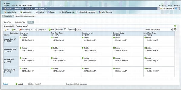
Currently, Cisco incorporates MACSec as a security feature under the Cisco TrustSec Framework

Reference: http://www.networkworld.com/details/7593.html?def

More about Cisco TrustSec Architecture

Friday, June 4, 2010

Musical Fountain @ Las Vegas

I like this musical fountain, which is just in front of Bellagios Hotel where I stayed in Mar earlier this year.

Thursday, June 3, 2010

SID duplication

Recently, I added a couple of VMs (Windows 2008 Server R2) from the same image. I did sysprep on the original image and just duplicate the VHD thinking that the sysprep process would reset the original SID. Depending on which point that you capture the VHD image after sysprep (i.e. SID is fixed once the Win7 logo appears), all subsequent duplicate VHD may still share the same SID as the first duplicate. I didn't realise it until I failed to add the duplicate VMs to a same security group. Hence, it's always recommended to capture the image right after the sysprep shutdown, so that you can re-use the same image again and again. (Hint: always shut and do not reboot after sysprep, which SID will be fixed during the initial booting process). 

In case of suspected SID duplication, there is this wonderful "name2sid" to find out if there's duplicate SID on the domain. Download it and check it against other servers, as well as the domain e.g.

name2sid contoso.com
name2sid Host01
name2sid Host02 and so forth

And there is also this blog post that mentioned about how to build an unattended installation XML and automated sysprep on the latest W2K8 R2 and Win7 images.

Wednesday, April 21, 2010

How to add device for SNMP Trap Monitoring in Nagios

SNMP Trap is pretty like syslog. It sends error messages to the Network Management System(NMS) like Nagios. Nagios doesn’t support SNMP trap by default. There is a Nagios plugin called SNMPTT that translate the received SNMP trap to the Nagios console. To install SNMPTT on Nagios, I used this guide "How to recieve SNMP Trap in Nagios". Afterwhich, you may follow the steps below to load additional SNMP MIBS trap for each managed device.

1) Load and compile MIBS to Nagios
This is the command to compile MIBS to Nagios server:
snmpttconvertmib --in= --out=/etc/snmp/snmptt.conf. --exec='/usr/local/nagios/libexec/eventhandlers/submit_check_result $r TRAP 1'

It would be tedious if there are too many MIBs files. Therefore, I wrote a simple bash script called “loadMIBS to compile all the MIBS in a folder.
if [ $# -ne 2 ]; then
echo "loadMIBS 'folder' 'device'"
exit 1
fi
for file in $( ls $1 ); do
/usr/sbin/snmpttconvertmib --in=$1\/$file \
--out=/etc/snmp/snmptt.conf.$2 \
--exec='/usr/local/nagios/libexec/eventhandlers/submit_check_result $r TRAP 1'
echo "MIBS loaded in /etc/snmp/snmptt.conf.$2"
done

2) Inform SNMPTT on the newly compiled Files
Modify /etc/snmp/snmptt.ini to include the earlier files:

[TrapFiles]
snmptt_conf_files =
/etc/snmp/snmptt.conf.devicename1
/etc/snmp/snmptt.conf.devicename2

END

3) Add the new Device to Nagios configuration file
I have created a standard file to consolidate all SNMP Trap devices at /usr/local/nagios/etc/objects/snmptrap.cfg. Just follow the example below:

define host{
use windows-server ; Inherit default values from a template
host_name HostA
alias HostA

address xx.xx.xx.xx ; IP address of the host
}

define host{
use windows-server ; Inherit default values from a template
host_name HostB
alias HostB
address xx.xx.xx.xx ; IP address of the host
}

define hostgroup{
hostgroup_name snmp_group ; The name of the hostgroup
alias SNMP TRAP
members HostA, HostB
}

define service{
hostgroup_name snmp_group
use snmptrap-service
contact_groups netadmin ; Who to alert & contact
}

4) Define New TRAP service on Nagios
Separately, on the templates.cfg, I have added this SNMP trap service
# define snmp trap service for network
define service{
use generic-service
name snmptrap-service
check_command check-host-alive
service_description TRAP
passive_checks_enabled 1
register 0
is_volatile 1
check_period none
max_check_attempts 1
normal_check_interval 1
retry_check_interval 1
notification_interval 31536000
notification_options w
}

Red: Make sure that the service description must match the submit_check_result parameter i.e. TRAP in this case. Otherwise, Nagios won't be able to match the recieved snmp trap to the passive service.

5) Verifying New SNMP Trap Service

Restart Nagios service and generate a test snmp trap from your managed device. If you do not receive an alert (email and/or sms), do the following:
  • Check that the snmp trap daemon is running i.e. ps -e | grep trap
  • Check the snmptt log that the trap is received
  • Click on the "Event Logs" of Nagios admin console. Check that the event handler "submit_check_result" is executed correctly.