In my earlier post "Setting up RADIUS authentication for Cisco devices", there is a set of example Cisco IOS commands to define the RADIUS server for Cisco authentication. However, it can't work if you apply VRF, even if you use the "ip radius source-interface" command.
If you have Cisco devices using Multi-VRF and/or MPLS related commands, you have to define "aaa group server" instead. Other advantages include server load-balancing and grouping them for different purposes, such dot1x and login etc. Below are the example commands.
(config)# aaa authentication login NetworkLogin group NetworkRadius local
! group up the servers
(config)# aaa group server radius NetworkRadius
(config-sg-radius)# server 1.1.1.1 auth-port 1812 acct-port 1813
! define VRF and source interface
(config-sg-radius)# ip vrf forwarding YOUR_VRF
(config-sg-radius)# ip radius source-interface Loopback 0
! define the radius server
(config)# radius-server host 1.1.1.1 auth-port 1812 acct-port 1813 timeout 5 key ****
! apply the RADIUS authentication list
(config)# line vty 0 4
(config-line)# login authentication NetworkLogin
To verify the configuration, do "show radius server-group all" on the exec mode.
Monday, November 29, 2010

Tuesday, November 16, 2010
RADIUS Shared Key Template
In one of the comments in my earlier post "Setting up RADIUS authentication for Cisco devices", someone asked whether he should have all network devices having different radius keys. Don't get it wrong, this is the shared key between the RADIUS server and the client (e.g. Cisco or other network security devices), which is a RADIUS requirement. We are not referring to the individual user credential used to gain administrative access into the Cisco devices or the network resources. Note that the same RADIUS protocol is also commonly used for other applications, such IEEE 802.1x, WPA2, remote dial-in etc. These applications would also face similar issue of having shared secret between the security device and the RADIUS server. See this RADIUS overview on Wiki.
I felt that might poised another more serious security issue. Imagine there can be hundreds of devices under his care, what if he lost or accidentally leaked that long password list?
To strike a good balance between manageability and security, I would advise that those less critical devices can share a common key while applying another common key for more sensitive/critical devices (fewer in number). For highly sensitive/critical devices, a unique key may be applied.
Fortunately, Microsoft RADIUS or the Network Policy Server (NPS) in Windows 2008 R2 provides shared secret template feature to facilitate that. A group of devices belonging to similar security level can share a common shared secret template.
To create a new template, open up NPS server console, expand on "Template Management", right-click on "Shared Secret" and add "New". A small windows would pop up:
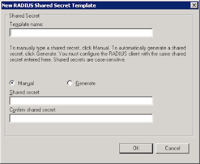
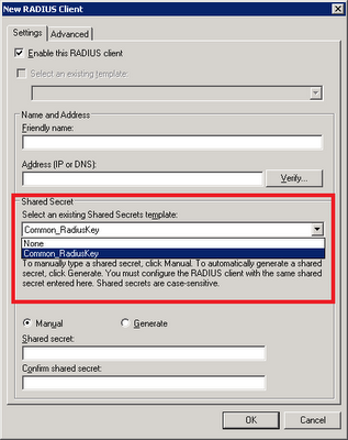
Give it a name and add in the shared secret. Click "Ok". On the properties of RADIUS client, select the relevant template on the drop-down box.
I felt that might poised another more serious security issue. Imagine there can be hundreds of devices under his care, what if he lost or accidentally leaked that long password list?
To strike a good balance between manageability and security, I would advise that those less critical devices can share a common key while applying another common key for more sensitive/critical devices (fewer in number). For highly sensitive/critical devices, a unique key may be applied.
Fortunately, Microsoft RADIUS or the Network Policy Server (NPS) in Windows 2008 R2 provides shared secret template feature to facilitate that. A group of devices belonging to similar security level can share a common shared secret template.
To create a new template, open up NPS server console, expand on "Template Management", right-click on "Shared Secret" and add "New". A small windows would pop up:

Give it a name and add in the shared secret. Click "Ok". On the properties of RADIUS client, select the relevant template on the drop-down box.

Sunday, October 10, 2010
Multicast for MPLS VPN
We need to transport multicast traffic across our enterprise MPLS core network for users to receive their favorite Channel News Asia and CNN live broadcasts on their workstations. I found this updated Cisco resource - Configuring Multicast VPN (MVPN) - for IOS 12.4, which is different from the older IOS versions. The newer version support MDT SAFI, which will be automatically created when the default MDT (Multicast Distribution Tree) exists. The default MDT defines the path used by PE routers to send multicast data and control messages to every other PE router in the multicast domain. The setting up of MDT involves the following steps:
Data MDTs, which are dynamically created, are intended for high-bandwidth sources such as full-motion video inside the VPN to ensure optimal traffic forwarding in the MPLS VPN core. When the multicast transmission exceeds the defined threshold, the sending PE router creates the data MDT and sends a UDP message, which contains information about the data MDT to all routers on the default MDT. The threshold at which the data MDT is created can be configured on a per-router or a per-VRF basis. However, Data MDTs are created only for shared tree (S, G) multicast route entries within the VRF multicast routing table. They are not created for source tree (*, G) entries regardless of the value of the individual source data rate.
- Configuring a Default MDT Group for a VRF (required)
- Configuring the MDT Address Family in BGP for Multicast VPN (required)
- Configuring the Data Multicast Group (optional)
Data MDTs, which are dynamically created, are intended for high-bandwidth sources such as full-motion video inside the VPN to ensure optimal traffic forwarding in the MPLS VPN core. When the multicast transmission exceeds the defined threshold, the sending PE router creates the data MDT and sends a UDP message, which contains information about the data MDT to all routers on the default MDT. The threshold at which the data MDT is created can be configured on a per-router or a per-VRF basis. However, Data MDTs are created only for shared tree (S, G) multicast route entries within the VRF multicast routing table. They are not created for source tree (*, G) entries regardless of the value of the individual source data rate.
Tuesday, September 21, 2010
MPLS MTU for Enterprise MPLS VPN
We are in the midst of building a new 10GE MPLS VPN for our enterprise campus core network. After we setup our first MPLS VPN, we are able to connect up 2 different VRFs (a.k.a virtual networks) belonging to 2 different departments. Ping test shows that the RTT was close to 0 msec. However, Active Directory traffic was slowed to a claw.
We investigated and found no fault at the routing and mpls configuration. Later, I recalled an experience of slow access over GRE tunnel relating to MTU sizing. Further search on Cisco.com revealed this:
We investigated and found no fault at the routing and mpls configuration. Later, I recalled an experience of slow access over GRE tunnel relating to MTU sizing. Further search on Cisco.com revealed this:
When configuring the network to use MPLS, set the core-facing interface MTU values greater than the edge-facing interface MTU values, using one of the following methods:
- Set the interface MTU values on the core-facing interfaces to a higher value than the interface MTU values on the customer-facing interfaces to accommodate any packet labels, such as MPLS labels, that an interface might encounter. Make sure that the interface MTUs on the remote end interfaces have the same interface MTU values. The interface MTU values on both ends of the link must match.
- Set the interface MTU values on the customer-facing interfaces to a lower value than the interface MTU on the core-facing interfaces to accommodate any packet labels, such as MPLS labels, than an interface might encounter. When you set the interface MTU on the edge interfaces, ensure that the interface MTUs on the remote end interfaces have the same values. The interface MTU values on both ends of the link must match.
We adopted the former approach and set MTU size of all core facing interfaces to 1520 bytes and leave all customer facing interfaces to default 1500 bytes.
Monday, August 23, 2010
Re-using old network connection name
Whenever you try to name a network connection name with the same name of once-existence old network adaptor, you would encounter this error

To use back the same name, execute the following command:
SET DEVMGR_SHOW_NONPRESENT_DEVICES=1
START DEVMGMT.MSC
On the Device Manager, click on View -> Show hidden device, uninstall the non-existence network device.

To use back the same name, execute the following command:
SET DEVMGR_SHOW_NONPRESENT_DEVICES=1
START DEVMGMT.MSC
On the Device Manager, click on View -> Show hidden device, uninstall the non-existence network device.
Wednesday, August 18, 2010
Setting up RADIUS authentication for Cisco devices
I know this is not new but would like to elaborate slightly further for my team. The "Network Policy Server" in Windows 2008 can serve as a central AAA mechanism for all Cisco logins. Furthermore, each network administrator can login using their individual credential (which is AD-integrated) instead of sharing a common set of local passwords, which is an administrative nightmare if these passwords are compromised.
This blog explained the initial setup. To continue adding more RADIUS client (i.e. Cisco devices), log on to the NPS server and fire up the Network Policy Server console.
1) Add RADIUS client
Right click on RADIUS client and click "New". Enter the name of device and the IP address. As a Cisco device may have multiple interfaces, I would prefer using the loopback address. Also, supply the pre-shared key between the server and the client.
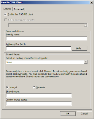
Note: Both IP addresses and the key must match. If not, authentication would fail.
2) Cisco Configuration
Cautious: Make sure you have another running line or console before you do this.
aaa new-model
#use radius login 1st. when time-out, use local password
#you may want to define your own list. Make sure the list in red must match the login vty below
aaa authentication login RadiusList group radius local
#make sure it matches the client IP address in the NAP server earlier
ip radius source-interface Loopback0
#replace the below brackets with your values
radius-server host [server_IP] auth-port 1812 acct-port 1813 timeout 5 key [your_key]
#apply authentication method
line vty 0 4
access-class MGMT_ACL in
logging synchronous
login authentication RadiusList
transport input ssh
3) Verifying & Troubleshooting
Try ssh into the device. If unsuccessful, check network connectivity from the client using "ping [server_IP] source loopback0". Run "debug radius" command and go to the event viewer of the server. For easy viewing, open up the Server Manager console and click on the "Network Policy Manager" where the login events are filtered automatically for you.
4) Change the prompt (Optional)
How do you know which are the devices use RADIUS or local authentication? Simple, just change the login & password prompts.
aaa authentication banner ^CAccess to this device is protected by NAP^C
aaa authentication password-prompt "NAP password:"
aaa authentication username-prompt "Your NAP id:"
This blog explained the initial setup. To continue adding more RADIUS client (i.e. Cisco devices), log on to the NPS server and fire up the Network Policy Server console.
1) Add RADIUS client
Right click on RADIUS client and click "New". Enter the name of device and the IP address. As a Cisco device may have multiple interfaces, I would prefer using the loopback address. Also, supply the pre-shared key between the server and the client.

Note: Both IP addresses and the key must match. If not, authentication would fail.
2) Cisco Configuration
Cautious: Make sure you have another running line or console before you do this.
aaa new-model
#use radius login 1st. when time-out, use local password
#you may want to define your own list. Make sure the list in red must match the login vty below
aaa authentication login RadiusList group radius local
#make sure it matches the client IP address in the NAP server earlier
ip radius source-interface Loopback0
#replace the below brackets with your values
radius-server host [server_IP] auth-port 1812 acct-port 1813 timeout 5 key [your_key]
#apply authentication method
line vty 0 4
access-class MGMT_ACL in
logging synchronous
login authentication RadiusList
transport input ssh
3) Verifying & Troubleshooting
Try ssh into the device. If unsuccessful, check network connectivity from the client using "ping [server_IP] source loopback0". Run "debug radius" command and go to the event viewer of the server. For easy viewing, open up the Server Manager console and click on the "Network Policy Manager" where the login events are filtered automatically for you.
4) Change the prompt (Optional)
How do you know which are the devices use RADIUS or local authentication? Simple, just change the login & password prompts.
aaa authentication banner ^CAccess to this device is protected by NAP^C
aaa authentication password-prompt "NAP password:"
aaa authentication username-prompt "Your NAP id:"
Sunday, August 15, 2010
RemoteFX coming in next SP of Win7 and Win2K8 R2
RemoteFX is an enhancement to RDP's graphics remoting capabilities. With Microsoft RemoteFX, users will be able to work remotely in a Windows Aero desktop environment, watch full-motion video, enjoy Silverlight animations, and run 3D applications – all with the fidelity of a local-like performance when connecting over the LAN. RemoteFX does this via a technique known as host-based rendering, which means the entire final composited screen image is rendered on the remote host and then compressed and sent down to the client.
Look like Microsoft is beefing up its RDP-based virtualizaton offering - namely Remote Desktop Services (RDS). The goal of RemoteFX is to deliver the full modern Windows desktop experience to the remote thin clients while their desktops are actually hosted in the data center as part of a virtual desktop infrastructure (VDI). And these virtual desktops must be hosted in Hyper-V.
We have been using Microsoft RDS to allow our network administrators to access their desktops and network management & troubleshooting tools from our standard locked down corporate PCs. And certainly, I'm looking forward to the next SP release, which promises the incorporation of RemoteFX. Probably, I should try out the beta release.
Look like Microsoft is beefing up its RDP-based virtualizaton offering - namely Remote Desktop Services (RDS). The goal of RemoteFX is to deliver the full modern Windows desktop experience to the remote thin clients while their desktops are actually hosted in the data center as part of a virtual desktop infrastructure (VDI). And these virtual desktops must be hosted in Hyper-V.
We have been using Microsoft RDS to allow our network administrators to access their desktops and network management & troubleshooting tools from our standard locked down corporate PCs. And certainly, I'm looking forward to the next SP release, which promises the incorporation of RemoteFX. Probably, I should try out the beta release.
Subscribe to:
Posts (Atom)