Monday, August 23, 2010

Re-using old network connection name

Whenever you try to name a network connection name with the same name of once-existence old network adaptor, you would encounter this error


To use back the same name, execute the following command:

SET DEVMGR_SHOW_NONPRESENT_DEVICES=1
START DEVMGMT.MSC

On the Device Manager, click on View -> Show hidden device, uninstall the non-existence network device.

Wednesday, August 18, 2010

Setting up RADIUS authentication for Cisco devices

I know this is not new but would like to elaborate slightly further for my team. The "Network Policy Server" in Windows 2008 can serve as a central AAA mechanism for all Cisco logins. Furthermore, each network administrator can login using their individual credential (which is AD-integrated) instead of sharing a common set of local passwords, which is an administrative nightmare if these passwords are compromised.

This blog explained the initial setup. To continue adding more RADIUS client (i.e. Cisco devices), log on to the NPS server and fire up the Network Policy Server console.

1) Add RADIUS client
Right click on RADIUS client and click "New". Enter the name of device and the IP address. As a Cisco device may have multiple interfaces, I would prefer using the loopback address. Also, supply the pre-shared key between the server and the client.


Note: Both IP addresses and the key must match. If not, authentication would fail.

2) Cisco Configuration
Cautious: Make sure you have another running line or console before you do this.

aaa new-model
#use radius login 1st. when time-out, use local password
#you may want to define your own list. Make sure the list in red must match the login vty below
aaa authentication login RadiusList group radius local
#make sure it matches the client IP address in the NAP server earlier
ip radius source-interface Loopback0
#replace the below brackets with your values
radius-server host [server_IP] auth-port 1812 acct-port 1813 timeout 5 key [your_key]

#apply authentication method
line vty 0 4
access-class MGMT_ACL in
logging synchronous
login authentication RadiusList
transport input ssh

3) Verifying & Troubleshooting
Try ssh into the device. If unsuccessful, check network connectivity from the client using "ping [server_IP] source loopback0". Run "debug radius" command and go to the event viewer of the server. For easy viewing, open up the Server Manager console and click on the "Network Policy Manager" where the login events are filtered automatically for you.

4) Change the prompt (Optional)
How do you know which are the devices use RADIUS or local authentication? Simple, just change the login & password prompts.

aaa authentication banner ^CAccess to this device is protected by NAP^C
aaa authentication password-prompt "NAP password:"
aaa authentication username-prompt "Your NAP id:"

Sunday, August 15, 2010

RemoteFX coming in next SP of Win7 and Win2K8 R2

RemoteFX is an enhancement to RDP's graphics remoting capabilities. With Microsoft RemoteFX, users will be able to work remotely in a Windows Aero desktop environment, watch full-motion video, enjoy Silverlight animations, and run 3D applications – all with the fidelity of a local-like performance when connecting over the LAN. RemoteFX does this via a technique known as host-based rendering, which means the entire final composited screen image is rendered on the remote host and then compressed and sent down to the client.

Look like Microsoft is beefing up its RDP-based virtualizaton offering - namely Remote Desktop Services (RDS). The goal of RemoteFX is to deliver the full modern Windows desktop experience to the remote thin clients while their desktops are actually hosted in the data center as part of a virtual desktop infrastructure (VDI). And these virtual desktops must be hosted in Hyper-V.

We have been using Microsoft RDS to allow our network administrators to access their desktops and network management & troubleshooting tools from our standard locked down corporate PCs. And certainly, I'm looking forward to the next SP release, which promises the incorporation of RemoteFX. Probably, I should try out the beta release.

Wednesday, August 4, 2010

Hyper-V live migration failed after configuration change

If you change the virtual host configuration (for example, add another virtual NIC) using Hyper-V MMC after the virtual host is "HAed", live migration would fail. To resolve this, remove the VM from the cluster and add it in again.


After some research on the Internet, I realised that you must not use Hyper-V MMC, use the "Setting" button in the Failover Clustering Manager instead. (Click below to enlarge)

Sunday, August 1, 2010

Part 2: How DNSSec works

This is the 2nd part of DNSSec. The 1st part introduce the prologue to DNSSec.

Overview
At the most basic level, DNSSEC provides the assurance for DNS servers and resolvers (a.k.a DNS clients) to trust DNS responses by using digital signatures for validation. Specifically, it provides origin authority, data integrity, and authenticated denial of existence of validated DNS responses.

When a DNS client issues a query for a name, the accompanying digital signature is returned in the response. Successful validation would show that the DNS response has not been modified or tampered with. Any subsequent modifications to the DNS zone (e.g. adding and deleting of records) would require the entire zone file to be re-signed.

Trust Anchor & PKI Concept
Before you can perform any digital signature validations, all involved parties must trust a common "authority" in higher level, in order to create a trust path beforehand. This "authority" is known as Trust Anchor, which is similar to the Certificate Authority (CA) in the PKI concept. Just like the PKI CA, it is also able to sign next-level child zones down under, such as child.abc.com if the trust anchor is on abc.com. Because everyone trust this common Anchor Point, the clients would also trust other "child zones" vouched by this "authority".
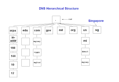
Do note that zone signing is only required for authoritative DNS servers. Remember that the DNS cache poisoning attacks are mostly targeted at the local DNS server caches of your ISPs. These recursive resolvers do not need to be signed by the root zone, as they are mostly non-authoritative (i.e. contain no zones on their owns) and simply perform recursive lookup on your behalf. The DNS resolvers belonging to the ISPs just need to be pre-configured to trust the public keys of the trust anchors - much like the Web browsers on your desktops that are pre-configured to trust the public certs of Verisign & Thawte.

New DNS Extension
To facilitate DNSSEC validations, four new resource records (DNSKEY, RRSIG, NSEC and DS) are introduced to existing DNS structure. DNSKEY (DNS public key) contains the zone public key. RRSIG (Resource Record Signature) contains the digital signature of the DNS response. NSEC (Next Secure) can inform about the denial-of-existence records. For example, if the zone only contains record A and D but you ask for B, it would return "A NSEC D" indicating the non-existence of records B and C. Lastly, DS (Delegation Signer) is used to validate between the parent and child zones, which are both DNSSec enabled.

IPSec
In most situations, the clients would simply ask the local DNS servers to perform DNSSec validation on their behalf. For maximum protection, you may also want to setup IPSec communications between the clients and the local servers. In corporate environments, these computers may use their domain certs for such domain IPSec setup. Note that IPSec is optional for DNSSec.

Name Resolution Policy Table (NRPT)
What if you wish to reject DNS response from non-DNSSec enabled DNS servers or making IPSec connection compulsory? You can influence such behaviours by the means of Name Resolution Policy Table (NRPT). Before issuing any queries, the DNS client will consult the NRPT to determine if any additional flags must be set in the query. Upon receiving the response, the client will again consult the NRPT to determine any special processing or policy requirements. In Windows Server 2008 R2 implementation, the following NRPT properties may be set using Group Policy:

1) Namespace: Used to indicate the namespace to which the policy applies. When a query is issued, the DNS client will compare the name in the query to all of the namespaces in this column to find a match.

2) DNSSEC: Used to indicate whether the DNS client should check for DNSSEC validation in the response. Selecting this option will not force the DNS server to perform DNSSEC validation. That validation is triggered by the presence of a trust anchor for the zone the DNS server is querying. Setting this value to true prompts the DNS client to check for the presence of the Authenticated Data bit in the response from the DNS server if the response has been validated, If not, the DNS client will ignore the response.

3) DNS Over IPsec: Used to indicate whether IPsec must be used to protect DNS traffic for queries belonging to the namespace. Setting this value to true will cause the DNS client to set up an IPsec connection to the DNS server before issuing the DNS query.

4) IPsec Encryption Level: Used to indicate whether DNS connections over IPsec will use encryption. If DNSOverIPsec is off, this value is ignored.

5) IPsec CA: Refers to the CA (or list of CAs) that issued the DNS server certificates for DNSSec over IPsec connections. The DNS client checks for the server authorization based on the server certificates issued by this CA. If left un-configured, all root CAs in the client computer’s stores are checked. If DNSOverIPsec is off, this value is ignored.

Saturday, July 31, 2010

Part 1: Prologue to DNS Security Extensions (DNSSec)

The Root DNS has recently been digitally signed (~2 weeks ago) as announced on its root DNS webpage. In other words, the signed root zone with actual key (as a root trust anchor) is now ready and available for validated DNS queries and transfers, including its security-aware child zones.

Microsoft also recently published an updated 80+ page implementation guide of DNSSec on Windows server 2008 R2. Note that DNSSec is not Microsoft or any vendor proprietary standard but is ratified by IETF in RFCs 4033, 4034, and 4035.

But why DNSSec is important? Everyone understands that DNS is the yellow-pages of Internet. However, it is weakly implemented in terms of security standards, as it is vulnerable to spoofing attacks, in particular DNS cache poisoning. To highlight its importance, we need to first understand the inherent security weaknesses on traditional DNS.

For the sake of efficiency, chances are you will be relying on your local ISP DNS servers to resolve all DNS queries by your favourite web browsers and email clients. Depending on the DNS configuration, the local DNS servers may conduct recursive queries all the way from the Intenet root zone to the respective domain authoritative servers or simply forward the queries to its "nearby" peers. (I suspect most DNS servers are configured in the latter mode rather than the former.) The obtained records will usually be locally cached for the use of subsequent queries until the expiry of TTL (Time-To-Live)

During this chain of recursive lookup, the resolver just weakly verifies the authenticity of the response based on some matching parameters (i.e. XID value, ports, addresses, and query types) that are sent in plain. Parameters, such as ports (default UDP 53) and remote server address value, can be easily guessed. Only XID value may present some challenge, as it is randomised. However, the challenge is not insurmountable, as it is only 16-bit long.


This weakness may allow a malicious attackers to guess the right values and send spoofed DNS response to your ISP servers, hoping to alter the cached DNS records. The malicious user can also increase his odds of success by sending many spoofed UDP response packets, each with different XID values. The attacker can insert any DNS data of his choosing into the response for the queried name and type. For example, the malicious user can place the IP address of his own server in a spoofed response to a query for the Web site of a bank like dbs.com.sg or online merchant. In another possible MITM (man-in-the-middle) attack scenario, a malicious network engineer in some large ISPs may plant a rogue DNS server to intercept any DNS queries from the smaller downstream ISPs and return any values that he wants. Obviously, the results can be catastrophic.

In my next post, I will discuss about how DNSSec can provide authentication and integrity protection to circumvent these attacks.

Sunday, July 25, 2010

Internet Load Balancing for Dual WAN Links to ISP

Recently, the WAN upgrade to our ISP is complete with dual redundant paths. We were asked if we could allow our Internet surfing users utilizing both links as much as possible instead of leaving one link to be idle most of the time. At the same time, it must not break the existing path redundancy. Since BGP rules Internet routing, we are using it to our advantage.

Below is the simplified network diagram to keep this discussion simple. (Click to enlarge)


Our 2 routers and the provider's routers are peered in full mesh eBGP. We advertised our public IP subnet (say 160.1.1.0/29) to the world via the 2 ISP routers (i.e. ISP R1 and ISP R2). By default in BGP, only 1 best route (i.e. default route) from either ISP R1 or ISP R2 is chosen as the path to the Internet. To influence the routing behavior, AS path prepend is used to influence inbound traffic and local preference to outbound traffic. As for load-balancing, whatever traffic that entered via R1 will route through ISP R1 and the similar applies to R2. This is our strategy for ISP link load-balancing:
  1. We further break our public IP subnet into 2 halves i.e. 160.1.1.0/30 and 160.1.1.4/30 and advertise them via both R1 and R2.
  2. On R1, we prepend AS path on advertised route 160.1.1.4/30 to make it less desirable for inbound traffic to use this route via R1. On R2, we prepend AS path on route 160.1.1.0/30.
  3. On R1, higher local preference is set for default route (0.0.0.0/32) advertised from ISP R1. Hence, ISP R1 will be the preferred next-hop for all outbound Internet traffic entered via R1. As for R2, the next preferred next-hop will be ISP R2.
  4. In summary, the path will become R1 <-> ISP R1 and R2 <-> ISP R2. We influence inbound traffic by making the other route less attractive and outbound traffic by making the route more attractive. If either R1 or R2 link were down, the remaining active link will take over all the traffic.

As for load-balancing between our routers (R1 & R2), it is more straightforward. Have both routers to advertise default route (on same metric) into the IGP (e.g. OSPF or RIP) by using "default information-orginate" router command. Alternatively, you may prefer GLBP (Gateway Load Balancing Protocol) for multiple clients.

The diagram (courtesy from my colleague MT) below illustrates the BGP load-balancing concept described above. (Click to enlarge)


Any sample configuration? Here you are:

On R1:
router bgp 65001
bgp router-id 172.16.1.1
bgp log-neighbor-changes
no auto-summary
neighbor 172.16.1.3 remote-as 65002
neighbor 172.16.1.3 route-map R1-ISPR1-MAP out # apply AS path prepend
neighbor 172.16.1.3 activate
neighbor 172.16.1.4 remote-as 65002
neighbor 172.16.1.4 route-map ISPR1-R1-MAP in # set higher local preference
neighbor 172.16.1.4 activate
no synchronization
network 160.1.1.0 mask 255.255.255.252 # route advertisement
network 160.1.1.4 mask 255.255.255.252
!
# exact routes must exist before they can be advertised in eBGP!
# since we are using NAT, just create some "phantom" routes
ip route 160.1.1.0 255.255.255.252 null0
ip route 160.1.1.4 255.255.255.252 null0
!
!
# Use NAT overload for internal users accessing Internet
ip nat pool INET_POOL 160.1.1.1 160.1.1.1 netmask 255.255.255.252
ip nat inside source list INSIDE_VLAN pool INET_POOL overload
!
ip access-list standard INSIDE_VLAN
permit 192.168.2.0 0.0.0.63
!
access-list 11 permit 160.1.1.0 0.0.0.3
access-list 12 permit 160.1.1.4 0.0.0.3
!
#make certain route advertised by this router less desirable
#to influence inbound traffic
route-map R1-ISPR1-MAP permit 10
match ip address 12
set as-path prepend 65001 65001 65001
!
route-map R1-ISP1-MAP permit 20
match ip address 11
!
#prefer default route from specific ISP router to influence outbound traffic
route-map ISPR1-R1-MAP permit 10
set local-preference 200

On R2:
router bgp 65001
bgp router-id 172.16.1.2
bgp log-neighbor-changes
no auto-summary
neighbor 172.16.1.3 remote-as 65002
neighbor 172.16.1.3 route-map ISPR2-R2-MAP in
neighbor 172.16.1.3 activate
neighbor 172.16.1.4 remote-as 65002
neighbor 172.16.1.4 route-map R2-ISPR2-MAP out
neighbor 172.16.1.4 activate
no synchronization
network 160.1.1.0 mask 255.255.255.252
network 160.1.1.4 mask 255.255.255.252
!
ip route 160.1.1.0 255.255.255.252 null0
ip route 160.1.1.4 255.255.255.252 null0
!
!
ip nat pool INET_POOL 160.1.1.5 160.1.1.5 netmask 255.255.255.252
ip nat inside source list INSIDE_VLAN pool INET_POOL overload
!
ip access-list standard INSIDE_VLAN
permit 192.168.2.0 0.0.0.63
!
access-list 11 permit 160.1.1.0 0.0.0.3
access-list 12 permit 160.1.1.4 0.0.0.3
!
route-map R2-ISPR2-MAP permit 10
match ip address 11
set as-path prepend 65001 65001 65001
!
route-map R2-ISP2-MAP permit 20
match ip address 12
!
route-map ISPR2-R2-MAP permit 10
set local-preference 200