After "accidentally" bringing a disk storage offline by clicking on the "Take this resource offline", the action items under the action panel for this disk resource just went disappear.
To bring the disk resource for the Hyper-V fail-over clustering back online, you have to use the "Cluster" command line:
1) To view current status and to capture the "disk-resource-name":
CLUSTER [cluster-name] RESOURCE /STATUS
2) To bring the disk resource back online:
CLUSTER [cluster-name] RESOURCE "disk-resource-name" /ONLINE
Wednesday, December 15, 2010

Saturday, December 11, 2010
Access-based Enumeration
How do you stop users from listing files on the network folders that they have no access rights? You have created network shared folders with the default rights of read access for "Everyone". Individual users could "see" the file & folder listing of their co-workers, even though they may not read the file contents.
Microsoft has this Access-based enumeration (ABE) feature that displays only the files and folders that a user has permissions to access. If a user does not have Read (or equivalent) permissions for a folder, Windows hides the folder from the user’s view.
Access-based enumeration can be manually enabled or disabled on individual shared folders and volumes by using Share and Storage Management. This snap-in is available after a folder or volume has been shared. You can access Share and Storage Management in the File Services server role in Server Manager, and in Administrative Tools. You can also install it manually in Server Manager by adding the File Server role service to File Services.
There are two ways to enable and disable access-based enumeration by using Share and Storage Management:
Access-based Enumeration Reference
Microsoft has this Access-based enumeration (ABE) feature that displays only the files and folders that a user has permissions to access. If a user does not have Read (or equivalent) permissions for a folder, Windows hides the folder from the user’s view.
Access-based enumeration can be manually enabled or disabled on individual shared folders and volumes by using Share and Storage Management. This snap-in is available after a folder or volume has been shared. You can access Share and Storage Management in the File Services server role in Server Manager, and in Administrative Tools. You can also install it manually in Server Manager by adding the File Server role service to File Services.
There are two ways to enable and disable access-based enumeration by using Share and Storage Management:
- Share a folder or volume by using the Provision a Shared Folder Wizard. If you select the SMB protocol on the Share Protocols page of the Provision a Shared Folder Wizard, the advanced settings options on the SMB Settings page includes the option to enable access-based enumeration on the shared folder or volume. (To see the advanced settings options, on the SMB Settings page of the wizard, click Advanced).
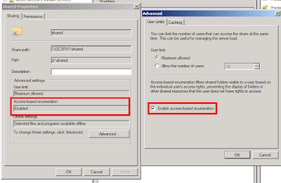
- Change the properties of an existing shared folder or volume. To change the properties of an existing shared folder or volume, on the Shares tab of Share and Storage Management, click the shared folder or volume, and then click Properties in the Action pane. The information under Advanced settings displays whether access-based enumeration is enabled. Click Advanced and then select or clear the Enable access-based enumeration check box.

Access-based Enumeration Reference
Wednesday, December 8, 2010
Bridging Dense-Mode PIM to Sparse-Mode PIM
For IP PIM multicast, Cisco recommends Sparse-Mode over Dense-Mode. In the midst of our network migration, we have a new network operating in Sparse-Mode with Anycast rendezvous point (RP) but our existing network is still operating in Dense-Mode. To bridge two different modes across both PIM domains, we should use the ip pim dense-mode proxy-register command on the interface leading toward the bordering dense mode region. This configuration will enable the border router to register traffic from the dense mode region (which has no concept of registration) with the RP in the sparse mode domain.
Click on below image for configuration example (extracted from this Cisco site).

Monday, December 6, 2010
Configuring Nexus 5000 with Nexus 2000 Fabric Extenders
Top-of-rack switching is commonly deployed for high port-density data centers. Switches are mounted at the top of each rack that makes cabling looks neat and tidy. However, it leads to switch managability issues dealing with multiple spanning-trees when you have hundreds of layer 2 switches - not to mention firmware upgrading. To resolve these issues, we are using Nexus 5000 with multiple fabric extenders (Nexus 2000). The N2K are just like the line cards to a chassis switch e.g. Catalyst 6500, except that N5K doesn't peform L3 functions like IP routing. This setup allows you to manage the whole bunch of switches as a single switch distributed all over the data center as shown below.

Between N5K and N2K, you may connect upto 4 x fiber links . That is giving you up to 40Gbps uplink per extender. As the Nexus are running on Cisco NX-OS, most switching commands are similar to the tradition Cisco IOS. However, the setup configuration is different. You need to perform the following steps:
1) Create a virtual fex chassis
switch(config)# fex 117
! set the number of links from N5K to N2K
switch(config-fex)# pinning max-links 1 (you may set up to 4 links)
2) Associate the N2K extenders to the fex chassis
switch(config)# interface e1/17
switch(config-if)# switchport mode fex-fabric
switch(config-if)# fex associate 117
3) To verify
switch# sh int e1/17 fex-intf
You may now configure the individual switch ports on the N2K extenders like normal Cisco switch ports. Unlike other Cisco switches, most switching features are not enabled by default. You'll have to turn them on manually using the "feature" command. For example, if you wish to configure EtherChannel, you have to enable LACP using "feature lacp" command.
Monday, November 29, 2010
RADIUS and VRF
In my earlier post "Setting up RADIUS authentication for Cisco devices", there is a set of example Cisco IOS commands to define the RADIUS server for Cisco authentication. However, it can't work if you apply VRF, even if you use the "ip radius source-interface" command.
If you have Cisco devices using Multi-VRF and/or MPLS related commands, you have to define "aaa group server" instead. Other advantages include server load-balancing and grouping them for different purposes, such dot1x and login etc. Below are the example commands.
(config)# aaa authentication login NetworkLogin group NetworkRadius local
! group up the servers
(config)# aaa group server radius NetworkRadius
(config-sg-radius)# server 1.1.1.1 auth-port 1812 acct-port 1813
! define VRF and source interface
(config-sg-radius)# ip vrf forwarding YOUR_VRF
(config-sg-radius)# ip radius source-interface Loopback 0
! define the radius server
(config)# radius-server host 1.1.1.1 auth-port 1812 acct-port 1813 timeout 5 key ****
! apply the RADIUS authentication list
(config)# line vty 0 4
(config-line)# login authentication NetworkLogin
To verify the configuration, do "show radius server-group all" on the exec mode.
If you have Cisco devices using Multi-VRF and/or MPLS related commands, you have to define "aaa group server" instead. Other advantages include server load-balancing and grouping them for different purposes, such dot1x and login etc. Below are the example commands.
(config)# aaa authentication login NetworkLogin group NetworkRadius local
! group up the servers
(config)# aaa group server radius NetworkRadius
(config-sg-radius)# server 1.1.1.1 auth-port 1812 acct-port 1813
! define VRF and source interface
(config-sg-radius)# ip vrf forwarding YOUR_VRF
(config-sg-radius)# ip radius source-interface Loopback 0
! define the radius server
(config)# radius-server host 1.1.1.1 auth-port 1812 acct-port 1813 timeout 5 key ****
! apply the RADIUS authentication list
(config)# line vty 0 4
(config-line)# login authentication NetworkLogin
To verify the configuration, do "show radius server-group all" on the exec mode.
Tuesday, November 16, 2010
RADIUS Shared Key Template
In one of the comments in my earlier post "Setting up RADIUS authentication for Cisco devices", someone asked whether he should have all network devices having different radius keys. Don't get it wrong, this is the shared key between the RADIUS server and the client (e.g. Cisco or other network security devices), which is a RADIUS requirement. We are not referring to the individual user credential used to gain administrative access into the Cisco devices or the network resources. Note that the same RADIUS protocol is also commonly used for other applications, such IEEE 802.1x, WPA2, remote dial-in etc. These applications would also face similar issue of having shared secret between the security device and the RADIUS server. See this RADIUS overview on Wiki.
I felt that might poised another more serious security issue. Imagine there can be hundreds of devices under his care, what if he lost or accidentally leaked that long password list?
To strike a good balance between manageability and security, I would advise that those less critical devices can share a common key while applying another common key for more sensitive/critical devices (fewer in number). For highly sensitive/critical devices, a unique key may be applied.
Fortunately, Microsoft RADIUS or the Network Policy Server (NPS) in Windows 2008 R2 provides shared secret template feature to facilitate that. A group of devices belonging to similar security level can share a common shared secret template.
To create a new template, open up NPS server console, expand on "Template Management", right-click on "Shared Secret" and add "New". A small windows would pop up:
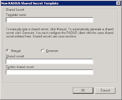
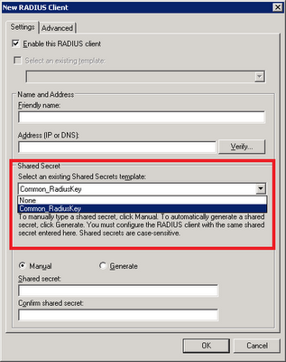
Give it a name and add in the shared secret. Click "Ok". On the properties of RADIUS client, select the relevant template on the drop-down box.
I felt that might poised another more serious security issue. Imagine there can be hundreds of devices under his care, what if he lost or accidentally leaked that long password list?
To strike a good balance between manageability and security, I would advise that those less critical devices can share a common key while applying another common key for more sensitive/critical devices (fewer in number). For highly sensitive/critical devices, a unique key may be applied.
Fortunately, Microsoft RADIUS or the Network Policy Server (NPS) in Windows 2008 R2 provides shared secret template feature to facilitate that. A group of devices belonging to similar security level can share a common shared secret template.
To create a new template, open up NPS server console, expand on "Template Management", right-click on "Shared Secret" and add "New". A small windows would pop up:

Give it a name and add in the shared secret. Click "Ok". On the properties of RADIUS client, select the relevant template on the drop-down box.

Sunday, October 10, 2010
Multicast for MPLS VPN
We need to transport multicast traffic across our enterprise MPLS core network for users to receive their favorite Channel News Asia and CNN live broadcasts on their workstations. I found this updated Cisco resource - Configuring Multicast VPN (MVPN) - for IOS 12.4, which is different from the older IOS versions. The newer version support MDT SAFI, which will be automatically created when the default MDT (Multicast Distribution Tree) exists. The default MDT defines the path used by PE routers to send multicast data and control messages to every other PE router in the multicast domain. The setting up of MDT involves the following steps:
Data MDTs, which are dynamically created, are intended for high-bandwidth sources such as full-motion video inside the VPN to ensure optimal traffic forwarding in the MPLS VPN core. When the multicast transmission exceeds the defined threshold, the sending PE router creates the data MDT and sends a UDP message, which contains information about the data MDT to all routers on the default MDT. The threshold at which the data MDT is created can be configured on a per-router or a per-VRF basis. However, Data MDTs are created only for shared tree (S, G) multicast route entries within the VRF multicast routing table. They are not created for source tree (*, G) entries regardless of the value of the individual source data rate.
- Configuring a Default MDT Group for a VRF (required)
- Configuring the MDT Address Family in BGP for Multicast VPN (required)
- Configuring the Data Multicast Group (optional)
Data MDTs, which are dynamically created, are intended for high-bandwidth sources such as full-motion video inside the VPN to ensure optimal traffic forwarding in the MPLS VPN core. When the multicast transmission exceeds the defined threshold, the sending PE router creates the data MDT and sends a UDP message, which contains information about the data MDT to all routers on the default MDT. The threshold at which the data MDT is created can be configured on a per-router or a per-VRF basis. However, Data MDTs are created only for shared tree (S, G) multicast route entries within the VRF multicast routing table. They are not created for source tree (*, G) entries regardless of the value of the individual source data rate.
Subscribe to:
Posts (Atom)