Wednesday, April 27, 2011

Price "inflation" for Microsoft exams from July 2011

IT certification is not shielded from the current world-wide commodity price inflation. From July 2011, Microsoft will raise most of its certification exam fees (~10% depending on regions). For Singapore, the price will be increased from SGD 225 to 246 for the TS and PRO series exams. Meanwhile, there is also an ongoing promotion (15-20% discount + free 2nd shot) till 30 Jun 2011.

So, hurry and sign up for the current promotion. Even if you're not ready, just book your first exam before 30 Jun and you still can have the free re-take until end of this year.

  1. New announcement on Microsoft exam fee
  2. Microsoft Exam Discount and free 2nd shot

Tuesday, April 26, 2011

Part 3: Configuring RIP routing on Windows Server 2008

This is following up on part 2 that described the concept of network high availability for single  non-clustered Windows server using dynamic IP routing. This final part is to outline implementation steps. On the Cisco routers, ensure that auto-summarization of RIP routing is disabled, as we are using /32 host addresses on the server loopback adapters.

Step 1: Install Windows loopback adapter
Add microsoft loopback adaptor using hardware wizard (hdwwiz.exe) with elevated admin rights. Assign a host IP address on it using /32 or 255.255.255.255 subnet mask. Add a host record statically on the DNS server using this IP address.

Step 2: Install “Routing and Remote Access Services” Server Role 
Open up Server Manager and add a server role named "Routing and Remote Access". Check on the following items:

Step 3: Add new routing protocol “RIP”
On the Server Manager console, right click on “Routing & Remote Access”, choose “Enable and Configure Routing ….” Click “Next”, select “Custom Configuration”. Select “LAN routing” and complete the wizard. Under “Routing and Remote Access > IPv4”, right click on “General” and choose “New Routing Protocol”. Select “RIPv2 for Internet Protocol”.

Step 4: Enable RIP on Network Adapter
Click on RIP and add new adapters (only public interfaces and loopback that you want users to access – never put in your management interface!). By default, Cisco routers would perform RIPv2 routing on multicast protocol, so select this option on the General tab.

For route optimization, it may be a good idea that your network routers to simply inject default routes into your server routing table. Click on "Advanced" tab and enable to following options:

You would also want to allow the server to advertise the host address (remember the loopback interface in step 1), which can be statically map to a host record on the DNS server.

Step 5: Securing RIP routing (Optional) (Important for better stability & security)
To prevent your server from listening to "rogue" RIP router/server that give bad routes, specify your trusted RIP neighbors on the Security tab (Right-click on RIP and choose Properties).

Furthermore, you probably won’t want your servers to become routers and carry network traffics unknowingly. You can further secure it by limiting it to advertise its own addresses only. For each interface added to RIP routing, choose “Properties”. Permit only the NIC address and the loopback address for outgoing routes.


Step 6: Verify IP routing
There are two ways to verify the IP routing table on your server, which should be populated by the network routers. You can view the IP routing table through the Routing And Remote Access console or through a command prompt. In the Routing And Remote Access console, expand the IP Routing node, right-click the Static Routes node, and then click Show IP Routing.


On the client network, do a continuous ping check (ping -t x.x.x.x) on the loopback address of the server. To simulate a NIC failure, disable one NIC and you may just see a couple of timeouts before resuming.

Monday, April 25, 2011

Using Anycast RP for Video Multicasting

In my earlier post on Bridging Dense-Mode to Sparse-Mode PIM, I mentioned about using Sparse-Mode Anycast Rendezvous Point (RP). But what is it about?

First of all, let's understand what Sparse-Mode Rendezvous Point is. For all multicast PIM, there is always at least one source (which is typically a video streaming server like the Microsoft Windows Media Services) and many client receivers. Instead of sourcing from the streaming server directly (as in the case of Source-Specific Multicast), multicast sources and receivers must register with their local rendezvous point (RP). So think of RP like a common meeting point for all sources and receivers. It is also known as a Shared Tree multicast model. In Cisco, there are a few configuration models for RP, including Manual RP (i.e. "hard-coding" of RP in every router), Auto-RP (i.e. elect one of many RP candidates), bootstrap RP (similar to Auto-RP) and Anycast RP.

Most RP models support only a single active RP at any one time. Only the Anycast RP model provides load sharing and redundancy in the multicast network. Anycast RP allows two or more rendezvous points (RPs) to share the load for source registration and the ability to act as hot backup routers for each other. Two or more RPs are configured with a common IP address on loopback interfaces with a 32-bit mask, making it a host address. All other routers are statically configured to map the RP to this common address and are likely to be linked up to the nearest RP. The protocol that links up multiple RPs is known as the Multicast Source Discovery Protocol (MSDP).

Static Anycast RP is also relatively easy to configure and troubleshoot. Consider the following example from Cisco.com:


As you can see from above example, both RP1 and RP2 share the common IP address of 10.0.0.1 on loopback 0 interface. MSDP is enabled to peer both RPs on the respective loopback 1 interfaces using the ip msdp commands. All other routers (the 2 routers at the bottom) just statically map the RP to this common IP address using the ip pim rp-address 10.0.0.1 command. Of course, you have to ensure that the loopback addresses are routable within your domain, which can be easily achieved in any dynamic IGP, such as OSPF.

Troubleshooting Summary
For troubleshooting, the most common failure is the breaking of Reverse Path Forwarding (RPF), which is a mechanism for the receiving routers to determine the best path to the source or the RP in this case. The most common omission is the missing  ip pim sparse-mode or ip pim sparse-dense-mode on all router interfaces.

After which still fail, have a client join to the multicast address. Alternatively,  you may simulate the joining by having the client's next-hop L3 access switch or router to join the multicast group using ip igmp join-group 239.1.1.1 (replace this address with the actual multicast address configured on your streaming server) on the receiver's interface level. Trace on every router from the receiver to the source using show ip mroute command (with vrf option in MPLS VPN or VRF-lite situation). Check for broken reverse path (.e.g. take note of missing RPF neighbor with Null incoming interface).

#show ip mroute 239.1.1.1
.....
(10.1.12.4, 239.1.1.1), 00:00:01/00:02:58, flags:
Incoming interface: Null, RPF nbr 0.0.0.0
Outgoing interface list:
Ethernet0/0, Forward/Dense, 00:00:02/00:00:00
Vlan111, Forward/Dense, 00:00:02/00:00:00

Take note of above output, if you see that the incoming interface is null and the neigbour is empty on a router (bold red), it usually means a missing "ip pim" on some interfaces or an issue on the underlying unicast routing issue. If it's latter, perform standard routing troubleshooting on the underlying IGP or static routes.

There is this good blog post that further elaborates the detailed steps on RPF troubleshooting.

Sunday, April 17, 2011

Part 2: Network Redundancy for Windows Server: Dynamic IP Routing

Besides NIC teaming in earlier part 1, another way to achieve network redundancy for Windows Server is to employ dynamic IP routing. Windows Servers support both static and dynamic IP routing. In dynamic routing, new routes are learned dynamically from the route peers (typically routers and L3 switches). Any changes in network topology (including failure of server NICs or switches) would trigger a routing update for all participating routing nodes. In other words, if there were any failure in any switches or NICs, traffic would have avoided the broken path and continue to route on unbroken links.


Examples of dynamic routing include Open Shortest Path First (OSPF) and Routing Information Protocol (RIP). Windows Server 2003 supports both OSPF and RIP while Windows Server 2008 only supports RIP. Besides achieving network redundancy, you need not configure routing statically, which is otherwise prone to network topology changes and configuration errors. Consider the following example:

Dual-homed ServerX is connected to 2 different switches on different subnets. RIPv2 routing is enabled on both NICs. By default, ServerX would dynamically register both DNS records with AD-integrated DNS servers. With DNS round-robin, network load-balancing can even be achieved among multiple clients. However, in the event of either NIC or switch failure, half of the clients would lose connection with ServerX, which is usually not desirable. Consider the next example:
MS Loopback adapter is installed. RIPv2 routing is enabled on two physical NICs, as well as the loopback adapter. Dynamic DNS update is also disabled. Single static A record is created with loopback IP address.  As dynamic routing supports equal-cost multi-path load-balancing, multiple clients reach ServerX loopback via both NICs. If either NIC or switch fails, dynamic routing would have to re-converge. After a short converging time, clients can regain access to ServerX on its loopback address via the sole remaining NIC.

In conclusion, with both dynamic routing and static DNS record on loopback adapter, both network load-balancing and network redundancy can be achieved. In my next post, I would summarize the steps to achieve this in part 3.

Wednesday, April 13, 2011

Part 1: Network Redundancy for Windows Servers: NIC Teaming

To provide network redundancy to a single Windows server, you would first need to have 2 or more NICs. To protect against a single switch failure, you would further need to ensure different NICs are connected to different network switches.

Generally, the most common way is to use hardware vendors' specific NIC teaming solutions, where multiple NICs are grouped and teamed into a single virtual network adapter. And you manage the Virtual Adapter just like how you manage a physical adapter. The most common NIC teaming solutions include:

For each of the vendor solutions, there are various teaming modes. Some protect against single NIC failure, single switch failure or even both (including load-balancing features). For Intel ANS, it supports the following teaming modes:

1) Adapter Fault Tolerance (AFT)
A team of 2 - 8 NICs connect to the same switch. Only 1 NIC is active and others on standby. Use one common IP address and MAC address. A 'failed' active adapter will pass its MAC and IP address to the standby adapter. As the name implied, it only protects against single NIC failure.

2) Switch Fault Tolerance (SFT)
Similar to AFT above, except that NICs are connected to different switches and supports only 2 NICs. In addition to single adapter protection, it protects against single switch failure.

3) Adaptive Load Balancing (ALB)
2 - 8 NICs can be teamed. One NIC receives and all ports transmit using one IP address and multiple MAC addresses. With Receive Load Balancing (RLB) enabled, more than one NIC (of the fastest speed) can receive traffic in load-balancing mode. Work with 1 or more switches.

4) Virtual Machine Load Balancing (VMLB)
Support multiple Hyper-V VMs on a team of 2 - 8 NICs. It provides transmit and receive traffic load balancing across multiple Virtual Machines (VM) bound to the common team interface. In a VMLB team, each VM is associated with one team member for its TX and RX traffic. If only one virtual NIC is bound to the team, or if Hyper-V is removed, then the VMLB team will act like an AFT team.

5) Link Aggregation
In Cisco term, it is known as EtherChannel where 2 - 8 NICs are teamed to the same switch. It uses a common virtual MAC address and IP address. It supports load-balancing across the team members.

NIC Teaming Configuration
Configuring Intel NIC teaming is a pretty straightforward task once you understand the basic network concept. For step-by-step, see this YouTube demo. Nevertheless, it is important to note that Microsoft (see KB254101 and KB968703) does not support vendor specific NIC teaming. If you raise support issues and NIC teaming is in suspect, MS may ask that the NIC teaming be removed.

In my next posting, I would talk about using Microsoft Windows 2008 Routing (RIPv2) for network redundancy as an alternative.

Saturday, April 9, 2011

Reverse Route Injection for VPN Remote Clients

In my previous post, I mentioned that Cisco ASA remote access can be easily setup using VPN wizard. One of the steps involve creating a IP address pool or DHCP server to assign dynamically inside IP addresses to the remote clients. Often, this range of IP addresses may not be routable in the trusted networks.

To resolve it, you either use NAT or Reverse Route Injection (RRI). For the latter, a static host route for the remote client would be injected into the IGP (e.g. RIP or OSPF), so that it would become routable. Enabling RRI is easy, on the ASDM conole, click on "Remote Access VPN > Network Access > Advanced > IPSec -> Crypto Maps". Edit an existing map, click on "Tunnel Policy (Crypto Map) - Advanced" tab and check on "Enable Reverse Route Injection".


Alternatively, on the command line, just append set reverse-route on the existing crypto map, e.g. "crypto dynamic-map SYSTEM_DEFAULT_CRYPTO_MAP 65535 set reverse-route".

Friday, April 8, 2011

Faster OSPF Convergence using iSPF

According to this Cisco config guide, OSPF uses Dijkstra's SPF algorithm to compute the shortest path tree (SPT). During the computation of the SPT, the shortest path to each node is discovered. The topology tree is used to populate the routing table with routes to IP networks. When changes to a Type-1 or Type-2 link-state advertisement (LSA) occur in an area, the entire SPT is recomputed.

In many cases, the entire SPT need not be recomputed because most of the tree remains unchanged. Incremental SPF (iSPF) allows the system to recompute only the affected part of the tree. Recomputing only a portion of the tree rather than the entire tree results in faster OSPF convergence and saves CPU resources. Note that if the change to a Type-1 or Type-2 LSA occurs in the calculating router itself, then the full SPT is performed. Incremental SPF is scheduled in the same way as the full SPF. Routers enabled with incremental SPF and routers not enabled with incremental SPF can function in the same internetwork.

Given only pros and not cons, we should enable iSPF by default. iSPF can be easily enabled using ispf command under each router ospf process.
  1. router ospf 1
  2. ispf
  3. !
To verify:
  1. show ip ospf 1 | inc SPF
  2. ........
  3. Incremental-SPF enabled 
  4. .......

    Thursday, April 7, 2011

    Cisco ASA Remote Access with external PKI

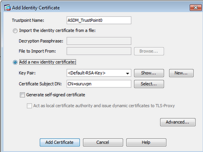
    It's trivial to setup Cisco ASA remote access by just running the "Remote Access" wizards. However, if you are relying on external PKI (e.g. Microsoft CA or OpenSSL) for certificate-based authentication, it can be a headache to troubleshoot. To minimize such hassles, try to import the CA cert and settle the VPN key-pairs before running the wizard. As for VPN certificate, I would recommend generating the cert request from Cisco ASDM console (i.e. self-enrollment) rather than importing, as the imported certificate may not contain the right constraints.

    To import the CA certificate, click on "Configuration > Remote Access VPN > Certificate Management > CA certificates > Add". To generate the new key-pair for the ASA, click one tab below on Identity Certificates and a dialog box would appear: Click on "New..." button, give it a new name and generate the new key-pair. Click on "Add Certificate" button and generate a p10 certificate request. Copy out the cert request file and send it over to the CA for issuance. In any case that you have to modify the X.509 attributes (e.g. CN, email etc), you don't have to re-generate a new key. Just delete away the old cert and re-use the same key for another new cert request. Run the step-by-step Remote Access Wizard.

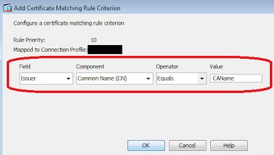
    However, the wizard won't set the default IKE profile to cert authentication. On "Advanced > IPSec > IKE Policies", create a highest priority (i.e. smallest number) on the IKE policies with authentication to "rsa-sig" or "authentication rsa-sig" under "crypto isakmp policy 1" on global config to ensure certificate authentication during the IKE phase. By default, the authentication would also be mapped to the default "DefaultRAGroup" instead of the newly generated profile. Click on "Advanced > IPSec > Certificate to Connection Profile Maps". This is to map the certificates to the right IPSec profile during the initial IKE authentication. Click on the "Add" button, create a new connection and map to your earlier wizard generated IPSec profile. Then click on the "Add button" below the Mapping Criteria for cert attribute matching. As all certificates in the chain have the same issuer, my preference is to match the Common Name (CN) of the issuing CA.

    On the front-end Cisco VPN client, you may choose any methods to enrol the client smart card or just by importing the p12 soft-tokens into the default Cisco store. Nothing much else is needed to configure on the front-end, except setting the destination host to the outside interface of your Cisco ASA VPN. Hopefully, there should be no errors. If there is, I find it easier to troubleshoot on the front-end client (rather than debugging on the back-end console) by enabling logging (Ctrl-E) and Ctrl-L to show the Log Window. Tweak the logging levels on the "Log Setting". The most common log sources would be the Certificates and IKE. If you wish, you may also turn on debugging on the backend using "debug crypto ca 127" and "debug crypto isakmp 127". Earlier, I saw a debug error on VPN client saying: Unable to establish Phase 1 SA with server because of "DEL_REASON_IKE_NEG_FAILED". Set the IKE authentication to auto by entering "isakmp identity auto" on the global config.

    Tuesday, April 5, 2011

    VRF-aware Dynamic Multipoint VPN

    Following on my previous post on VRF-aware Multipoint GRE, you can further protect the mGRE tunnels with IPSec easily.

    1. On all Routers

    2. !

    3. crypto keyring ciscokey vrf outer

    4. pre-shared-key address 172.16.0.0 255.255.0.0 key cisco123

    5. !

    6. crypto isakmp profile isaDMVPN

    7. keyring ciscokey

    8. match identity address 172.16.0.0 255.255.0.0 outer

    9. !

    10. crypto ipsec transform-set tfDMVPN esp-aes esp-sha-hmac

    11. mode transport

    12. !

    13. crypto ipsec profile proDMVPN

    14. set security-association lifetime seconds 900

    15. set transform-set tfDMVPN set isakmp-profile isaDMVPN

    16. !

    17. interface Tunnel1

    18. ip vrf forwarding inner

    19. tunnel protection ipsec profile proDMVPN #apply protection on tunnel

    To verify, perform the following commands and check the status in bold:

    1. Router1#sh crypto isakmp sa

    2. IPv4 Crypto ISAKMP SA

    3. dst src state conn-id slot status

    4. 172.16.1.1 172.16.1.2 QM_IDLE 1001 0 ACTIVE

    5. ......

    6. Router1#sh crypto session

    7. Crypto session current status

    8. Interface: Tunnel1

    9. Profile: isaDMVPN

    10. Session status: UP-ACTIVE

    11. ......

    If you couldn't obtain the above results, perform further troubleshooting using "debug crypto isakmp" and "debug crypto ipsec". Most of the time, the issues are related to isakmp issues and authentication key. Check that all the parameters (esp pre-shared key) can match.

    Monday, April 4, 2011

    VRF-aware Multipoint GRE Tunnel

    GRE tunnel is especially useful to encapsulate network traffic (including IGP routing) separate from the underlying infrastructure. One useful way is to create a logical Out-of-Band (OOB) management interface for network management on another VRF. The default point-to-point GRE tunnels are easy to setup when you have few remote sites to connect to. It will become less scalable, as the number of sites grow. To overcome it, consider point-to-multipoint tunnel instead. Instead of having multiple tunnels on the Hub router, you can have just one tunnel to connect to all spoke sites. And you don't have to manually map all the spoke destination addresses, as all the spoke routers will register dynamically with the Hub router. Consider the following diagram (click to enlarge):
    Assuming that the outer VRF (including the loopback interfaces) is already made routable (e.g. OSPF, BGP etc) within this network. We are setting up another VRF on the inner for network management purposes.

    1. On Hub CE Router A:
    2. interface Tunnel1
    3. ip vrf forwarding inner
    4. ip address 192.168.1.1 255.255.255.0
    5. ip nhrp authentication cisco #ensure matching key for all spokes
    6. ip nhrp map multicast dynamic
    7. ip nhrp network-id 123 #also ensure network-id can match
    8. ip ospf network broadcast
    9. ip ospf priority 10
    10. tunnel source Loopback0 #note that the destination is not defined
    11. tunnel mode gre multipoint
    12. tunnel key 123 # and the tunnel key as well
    13. tunnel vrf outer # create a tunnel on the outer vrf
    14. !
    15. router ospf 120 vrf inner
    16. network 172.16.1.1 0.0.0.0 area 0
    17. network 192.168.1.0 0.0.0.255 area 0


    1. On spoke router B
    2. interface Tunnel1
    3. ip vrf forwarding inner
    4. ip address 192.168.1.2 255.255.255.0
    5. ip nhrp authentication cisco
    6. ip nhrp map 192.168.1.1 10.1.1.1 #map inner vrf to outer vrf on hub router
    7. ip nhrp map multicast 10.1.1.1 #register with nhrp hub using multicast
    8. ip nhrp network-id 123
    9. ip nhrp nhs 192.168.1.1 #define hub router as next hop
    10. ip ospf network broadcast
    11. ip ospf priority 0
    12. tunnel source Loopback0
    13. tunnel mode gre multipoint
    14. tunnel key 123
    15. tunnel vrf outer
    16. !
    17. router ospf 120 vrf inner
    18. network 172.16.1.2 0.0.0.0 area 0
    19. network 192.168.1.0 0.0.0.255 area 0

    1. On spoke router C
    2. interface Tunnel1
    3. ip vrf forwarding inner
    4. ip address 192.168.1.3 255.255.255.0
    5. ip nhrp authentication cisco
    6. ip nhrp map 192.168.1.1 10.1.1.1 #map inner vrf to outer vrf on hub router
    7. ip nhrp map multicast 10.1.1.1 #register with nhrp hub using multicast
    8. ip nhrp network-id 123
    9. ip nhrp nhs 192.168.1.1 #define hub router as next hop
    10. ip ospf network broadcast
    11. ip ospf priority 0
    12. tunnel source Loopback0
    13. tunnel mode gre multipoint
    14. tunnel key 123
    15. tunnel vrf outer
    16. !
    17. router ospf 120 vrf inner
    18. network 172.16.1.3 0.0.0.0 area 0
    19. network 192.168.1.0 0.0.0.255 area 0

    If you have a second Hub router on the headend, you can setup another multippoint tunnel for redundancy like the following diagram:
    Nevertheless, the newly created overlay VPN remains in plain. You may also wish to protect it using IPSec. Cisco calls this combination of IPSec and Multipoint GRE as "Dynamic Multipoint VPN" or "DMVPN", which I should blog about it in my next post.

    Friday, April 1, 2011

    Cisco Performance Routing (PfR)

    For most medium-to-large networks, you would usually have more than 1 ISP to connect the enterprise network to all the remote sites. Traditional routing (such as OSPF, BGP etc) could route network traffic through a preferred path or load-balance among different paths. It can also automatically change path when a link is dead.

    However, traditional routing alone can't detect and take actions on links that are "half-dead" e.g. congested, flappy link etc. To overcome it, Cisco introduces Performance Routing (PfR) or f.k.s Optimized Edge Routing (OER) and add intelligence bits into the classical IP routing. There are two components to PfR: a Master Controller (MC) and a Border Router (BR). In a typical installation, there is one MC and one or more BRs. In many smaller designs, you can have the MC and BR on the same physical router.

    The MC is the brain of PfR. The MC receives performance data from the BRs, compares it against the configured policy, selects the best route for the data and sends commands to the BR to forward traffic to that path.

    The BR is the foot soldier of PfR. It collects the performance data and sends it to the MC. The MC compares the data against the configured performance policy. If it is out of policy, the MC sends commands to the BR to change the data path. PfR can monitor link performance based on passive mode (using netflow) and active mode (IP SLA).

    There is this good wiki article that explains the fundamental of PfR.