Thursday, December 30, 2010

Publish Offline Certificates and CRLs to Active Directory

This is refering to step 2 and 3 of the earlier post. Before publishing the Root CA cert, check the extensions on the Root CA server, esp on the CRL Distrisbution Point (CDP) extensions.

To publish the offline Root CA cert and CRL to AD, set the "Include in all CRLs" flag in the Root CA extension properties and use the certutil -dspublish command. Do note that file share CDP (FILE://) is not supported - only LDAP:// and HTTP://. I have tried and it's not going to work. Similarly, you would need to specify where clients and servers can obtain the root cert (i.e. LDAP and/or HTTP) in the "Authority Information Access (AIA)" drop-down setting.


The "Include in all CRLs" flag specifies that the Active Directory publication location should be included in the CRL itself. It can be used by an offline CA to specify the LDAP URL for manually publishing CRLs on the Active Directory. The explicit configuration container must be explicitly set in the URL. Alternatively, the DSConfigDN value can be set in the registry by using "certutil –setreg ca\DSConfigDN CN=Configuration,DC=contoso,DC=com". Note that the last two DC values (DC=contoso,DC=com for "contoso.com") are to be replaced by your actual Domain Name.


Export out the Root CA cert and CRL files and import them into a domain member server.
To publish the Root Cert to the Root CA store on the Active Directory: certutil -f -dspublish RootCA.cer RootCA 

To publish the CRL to Active Directory: certutil -f -dspublish Root-Test-CA.crl "LoneSrv1" "Root-Test-CA". The last 2 parameters to specify the containers are optional but could be needed if the offline RootCA is non-Microsoft.

Setting up Two-Tier Enterprise PKI


We are setting up a 2-tier CA for our enterprise PKI. The first tier is a standalone CA that should be kept offline while the second tier is the domain CA server that is used for issuing certificates for AD users and computers alike. Basically, these are the steps:

Step 0: If AD levels are below Windows 2008, perform adprep on Schema OM first i.e. "adprep /forestprep" and "adprep /domainprep /gpprep" on \supports\adprep DVD folder.
Step 1: Create CAPolicy.inf and place it on the %systemroot% folder. Optional step for Windows Server 2008 CA.
Step 2: Install standalone offline Root CA (RCA) server.
Step 3: Determine AIA  and CDP locations to host CRL from RCA. Configure the necessary extensions.
Step 4: Export out RCA cert and CRL. Publish root CA cert and CRL to Active Directory
Step 5: Setup Subordinate Issuing CA (Sub ICA) server.
Step 6: Create manual ICA cert request to Root CA for issuance. Install ICA cert.
Step 7: Setup Online Responder (OR). Configure OCSP template on ICA. Permit OR to autoenroll. Assign "Full Control" rights to "Network Services" on "Manage Private Key".
Step 8: Configure OR to provide revocation info for CAs. Input sources for CRL info using setup wizard e.g. LDAP etc
Step 9: Create new Cert Template by duplicating sample template for client enrollment
Step 10: Configure Group Policy to facilitate cert enrollment
Step 11: Use PKIView.msc and "certutil -url" to verify and check the health of PKI.

As for creating CAPolicy.inf, there is a good TechNet blog on its syntax. For Windows 2003 Root CA, CAPolicy.inf is essential to eliminate AIA and CDP extensions, so that applications would not have to validate the CDP of the entire chain, including the Root CA. AIA and CDP are revocation mechanism to verify the legitimacy of the entity, which would be meaningless for Root CA (the Anchor of Trust). For Windows 2008 Root CA, AIA and CDP are omitted by default. Nevertheless, CAPolicy.inf is still useful if you wish to include some policy statements or restricting the CA for certain purposes only, such as Secure Email.

If AIA is specified, Online Responder (new CA role in Windows Server 2008) should be activated for certificate revocation check. More detailed step-by-step guide for Online Responder can be found on TechNet.

In the next post, I would mention about publishing offline cert and crl files on Active Directory.

Wednesday, December 15, 2010

Bring Disk Storage back Online in Failover Clustering

After "accidentally" bringing a disk storage offline by clicking on the "Take this resource offline", the action items under the action panel for this disk resource just went disappear.

To bring the disk resource for the Hyper-V fail-over clustering back online, you have to use the "Cluster" command line:

1) To view current status and to capture the "disk-resource-name":
CLUSTER [cluster-name] RESOURCE /STATUS

2) To bring the disk resource back online:
CLUSTER [cluster-name] RESOURCE "disk-resource-name" /ONLINE

Saturday, December 11, 2010

Access-based Enumeration

How do you stop users from listing files on the network folders that they have no access rights? You have created network shared folders with the default rights of read access for "Everyone". Individual users could "see" the file & folder listing of their co-workers, even though they may not read the file contents.

Microsoft has this Access-based enumeration (ABE) feature that displays only the files and folders that a user has permissions to access. If a user does not have Read (or equivalent) permissions for a folder, Windows hides the folder from the user’s view.

Access-based enumeration can be manually enabled or disabled on individual shared folders and volumes by using Share and Storage Management. This snap-in is available after a folder or volume has been shared. You can access Share and Storage Management in the File Services server role in Server Manager, and in Administrative Tools. You can also install it manually in Server Manager by adding the File Server role service to File Services.

There are two ways to enable and disable access-based enumeration by using Share and Storage Management:
  1. Share a folder or volume by using the Provision a Shared Folder Wizard. If you select the SMB protocol on the Share Protocols page of the Provision a Shared Folder Wizard, the advanced settings options on the SMB Settings page includes the option to enable access-based enumeration on the shared folder or volume. (To see the advanced settings options, on the SMB Settings page of the wizard, click Advanced).
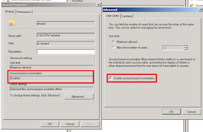
  2. Change the properties of an existing shared folder or volume. To change the properties of an existing shared folder or volume, on the Shares tab of Share and Storage Management, click the shared folder or volume, and then click Properties in the Action pane. The information under Advanced settings displays whether access-based enumeration is enabled. Click Advanced and then select or clear the Enable access-based enumeration check box.


Access-based Enumeration Reference

Wednesday, December 8, 2010

Bridging Dense-Mode PIM to Sparse-Mode PIM

For IP PIM multicast, Cisco recommends Sparse-Mode over Dense-Mode. In the midst of our network migration, we have a new network operating in Sparse-Mode with Anycast rendezvous point (RP) but our existing network is still operating in Dense-Mode. To bridge two different modes across both PIM domains, we should use the ip pim dense-mode proxy-register command on the interface leading toward the bordering dense mode region. This configuration will enable the border router to register traffic from the dense mode region (which has no concept of registration) with the RP in the sparse mode domain.

Click on below image for configuration example (extracted from this Cisco site).


Monday, December 6, 2010

Configuring Nexus 5000 with Nexus 2000 Fabric Extenders

Top-of-rack switching is commonly deployed for high port-density data centers. Switches are mounted at the top of each rack that makes cabling looks neat and tidy. However, it leads to switch managability issues dealing with multiple spanning-trees when you have hundreds of layer 2 switches - not to mention firmware upgrading. To resolve these issues, we are using Nexus 5000 with multiple fabric extenders (Nexus 2000). The N2K are just like the line cards to a chassis switch e.g. Catalyst 6500, except that N5K doesn't peform L3 functions like IP routing. This setup allows you to manage the whole bunch of switches as a single switch distributed all over the data center as shown below.


Between N5K and N2K, you may connect upto 4 x fiber links . That is giving you up to 40Gbps uplink per extender. As the Nexus are running on Cisco NX-OS, most switching commands are similar to the tradition Cisco IOS. However, the setup configuration is different. You need to perform the following steps:

1) Create a virtual fex chassis
switch(config)# fex 117
! set the number of links from N5K to N2K
switch(config-fex)# pinning max-links 1 (you may set up to 4 links)
2) Associate the N2K extenders to the fex chassis
switch(config)# interface e1/17
switch(config-if)# switchport mode fex-fabric
switch(config-if)# fex associate 117
3) To verify
switch# sh int e1/17 fex-intf

You may now configure the individual switch ports on the N2K extenders like normal Cisco switch ports. Unlike other Cisco switches, most switching features are not enabled by default. You'll have to turn them on manually using the "feature" command. For example, if you wish to configure EtherChannel, you have to enable LACP using "feature lacp" command.

Monday, November 29, 2010

RADIUS and VRF

In my earlier post "Setting up RADIUS authentication for Cisco devices", there is a set of example Cisco IOS commands to define the RADIUS server for Cisco authentication. However, it can't work if you apply VRF, even if you use the "ip radius source-interface" command.

If you have Cisco devices using Multi-VRF and/or MPLS related commands, you have to define "aaa group server" instead. Other advantages include server load-balancing and grouping them for different purposes, such dot1x and login etc. Below are the example commands.

(config)# aaa authentication login NetworkLogin group NetworkRadius local
! group up the servers
(config)# aaa group server radius NetworkRadius
(config-sg-radius)# server 1.1.1.1 auth-port 1812 acct-port 1813

! define VRF and source interface
(config-sg-radius)# ip vrf forwarding YOUR_VRF
(config-sg-radius)# ip radius source-interface Loopback 0
! define the radius server
(config)# radius-server host 1.1.1.1 auth-port 1812 acct-port 1813 timeout 5 key ****
! apply the RADIUS authentication list
(config)# line vty 0 4
(config-line)# login authentication NetworkLogin

To verify the configuration, do "show radius server-group all" on the exec mode.

Tuesday, November 16, 2010

RADIUS Shared Key Template

In one of the comments in my earlier post "Setting up RADIUS authentication for Cisco devices", someone asked whether he should have all network devices having different radius keys. Don't get it wrong, this is the shared key between the RADIUS server and the client (e.g. Cisco or other network security devices), which is a RADIUS requirement. We are not referring to the individual user credential used to gain administrative access into the Cisco devices or the network resources. Note that the same RADIUS protocol is also commonly used for other applications, such IEEE 802.1x, WPA2, remote dial-in etc. These applications would also face similar issue of having shared secret between the security device and the RADIUS server. See this RADIUS overview on Wiki.

I felt that might poised another more serious security issue. Imagine there can be hundreds of devices under his care, what if he lost or accidentally leaked that long password list?

To strike a good balance between manageability and security, I would advise that those less critical devices can share a common key while applying another common key for more sensitive/critical devices (fewer in number). For highly sensitive/critical devices, a unique key may be applied.

Fortunately, Microsoft RADIUS or the Network Policy Server (NPS) in Windows 2008 R2 provides shared secret template feature to facilitate that. A group of devices belonging to similar security level can share a common shared secret template.

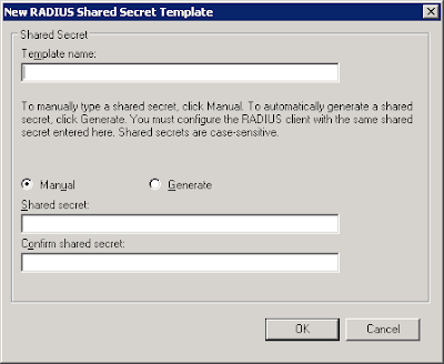
To create a new template, open up NPS server console, expand on "Template Management", right-click on "Shared Secret" and add "New". A small windows would pop up:


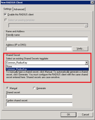
Give it a name and add in the shared secret. Click "Ok". On the properties of RADIUS client, select the relevant template on the drop-down box.

Sunday, October 10, 2010

Multicast for MPLS VPN

We need to transport multicast traffic across our enterprise MPLS core network for users to receive their favorite Channel News Asia and CNN live broadcasts on their workstations. I found this updated Cisco resource - Configuring Multicast VPN (MVPN) - for IOS 12.4, which is different from the older IOS versions. The newer version support MDT SAFI, which will be automatically created when the default MDT (Multicast Distribution Tree) exists. The default MDT defines the path used by PE routers to send multicast data and control messages to every other PE router in the multicast domain. The setting up of MDT involves the following steps:

  1. Configuring a Default MDT Group for a VRF (required)

  2. Configuring the MDT Address Family in BGP for Multicast VPN (required)

  3. Configuring the Data Multicast Group (optional)

Data MDTs, which are dynamically created, are intended for high-bandwidth sources such as full-motion video inside the VPN to ensure optimal traffic forwarding in the MPLS VPN core. When the multicast transmission exceeds the defined threshold, the sending PE router creates the data MDT and sends a UDP message, which contains information about the data MDT to all routers on the default MDT. The threshold at which the data MDT is created can be configured on a per-router or a per-VRF basis. However, Data MDTs are created only for shared tree (S, G) multicast route entries within the VRF multicast routing table. They are not created for source tree (*, G) entries regardless of the value of the individual source data rate.

Tuesday, September 21, 2010

MPLS MTU for Enterprise MPLS VPN

We are in the midst of building a new 10GE MPLS VPN for our enterprise campus core network. After we setup our first MPLS VPN, we are able to connect up 2 different VRFs (a.k.a virtual networks) belonging to 2 different departments. Ping test shows that the RTT was close to 0 msec. However, Active Directory traffic was slowed to a claw.

We investigated and found no fault at the routing and mpls configuration. Later, I recalled an experience of slow access over GRE tunnel relating to MTU sizing. Further search on Cisco.com revealed this:

When configuring the network to use MPLS, set the core-facing interface MTU values greater than the edge-facing interface MTU values, using one of the following methods:

  • Set the interface MTU values on the core-facing interfaces to a higher value than the interface MTU values on the customer-facing interfaces to accommodate any packet labels, such as MPLS labels, that an interface might encounter. Make sure that the interface MTUs on the remote end interfaces have the same interface MTU values. The interface MTU values on both ends of the link must match.
  • Set the interface MTU values on the customer-facing interfaces to a lower value than the interface MTU on the core-facing interfaces to accommodate any packet labels, such as MPLS labels, than an interface might encounter. When you set the interface MTU on the edge interfaces, ensure that the interface MTUs on the remote end interfaces have the same values. The interface MTU values on both ends of the link must match.

We adopted the former approach and set MTU size of all core facing interfaces to 1520 bytes and leave all customer facing interfaces to default 1500 bytes.

Monday, August 23, 2010

Re-using old network connection name

Whenever you try to name a network connection name with the same name of once-existence old network adaptor, you would encounter this error


To use back the same name, execute the following command:

SET DEVMGR_SHOW_NONPRESENT_DEVICES=1
START DEVMGMT.MSC

On the Device Manager, click on View -> Show hidden device, uninstall the non-existence network device.

Wednesday, August 18, 2010

Setting up RADIUS authentication for Cisco devices

I know this is not new but would like to elaborate slightly further for my team. The "Network Policy Server" in Windows 2008 can serve as a central AAA mechanism for all Cisco logins. Furthermore, each network administrator can login using their individual credential (which is AD-integrated) instead of sharing a common set of local passwords, which is an administrative nightmare if these passwords are compromised.

This blog explained the initial setup. To continue adding more RADIUS client (i.e. Cisco devices), log on to the NPS server and fire up the Network Policy Server console.

1) Add RADIUS client
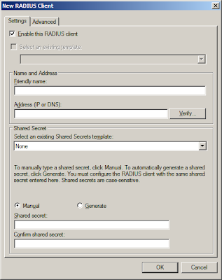
Right click on RADIUS client and click "New". Enter the name of device and the IP address. As a Cisco device may have multiple interfaces, I would prefer using the loopback address. Also, supply the pre-shared key between the server and the client.


Note: Both IP addresses and the key must match. If not, authentication would fail.

2) Cisco Configuration
Cautious: Make sure you have another running line or console before you do this.

aaa new-model
#use radius login 1st. when time-out, use local password
#you may want to define your own list. Make sure the list in red must match the login vty below
aaa authentication login RadiusList group radius local
#make sure it matches the client IP address in the NAP server earlier
ip radius source-interface Loopback0
#replace the below brackets with your values
radius-server host [server_IP] auth-port 1812 acct-port 1813 timeout 5 key [your_key]

#apply authentication method
line vty 0 4
access-class MGMT_ACL in
logging synchronous
login authentication RadiusList
transport input ssh

3) Verifying & Troubleshooting
Try ssh into the device. If unsuccessful, check network connectivity from the client using "ping [server_IP] source loopback0". Run "debug radius" command and go to the event viewer of the server. For easy viewing, open up the Server Manager console and click on the "Network Policy Manager" where the login events are filtered automatically for you.

4) Change the prompt (Optional)
How do you know which are the devices use RADIUS or local authentication? Simple, just change the login & password prompts.

aaa authentication banner ^CAccess to this device is protected by NAP^C
aaa authentication password-prompt "NAP password:"
aaa authentication username-prompt "Your NAP id:"

Sunday, August 15, 2010

RemoteFX coming in next SP of Win7 and Win2K8 R2

RemoteFX is an enhancement to RDP's graphics remoting capabilities. With Microsoft RemoteFX, users will be able to work remotely in a Windows Aero desktop environment, watch full-motion video, enjoy Silverlight animations, and run 3D applications – all with the fidelity of a local-like performance when connecting over the LAN. RemoteFX does this via a technique known as host-based rendering, which means the entire final composited screen image is rendered on the remote host and then compressed and sent down to the client.

Look like Microsoft is beefing up its RDP-based virtualizaton offering - namely Remote Desktop Services (RDS). The goal of RemoteFX is to deliver the full modern Windows desktop experience to the remote thin clients while their desktops are actually hosted in the data center as part of a virtual desktop infrastructure (VDI). And these virtual desktops must be hosted in Hyper-V.

We have been using Microsoft RDS to allow our network administrators to access their desktops and network management & troubleshooting tools from our standard locked down corporate PCs. And certainly, I'm looking forward to the next SP release, which promises the incorporation of RemoteFX. Probably, I should try out the beta release.

Wednesday, August 4, 2010

Hyper-V live migration failed after configuration change

If you change the virtual host configuration (for example, add another virtual NIC) using Hyper-V MMC after the virtual host is "HAed", live migration would fail. To resolve this, remove the VM from the cluster and add it in again.


After some research on the Internet, I realised that you must not use Hyper-V MMC, use the "Setting" button in the Failover Clustering Manager instead. (Click below to enlarge)

Sunday, August 1, 2010

Part 2: How DNSSec works

This is the 2nd part of DNSSec. The 1st part introduce the prologue to DNSSec.

Overview
At the most basic level, DNSSEC provides the assurance for DNS servers and resolvers (a.k.a DNS clients) to trust DNS responses by using digital signatures for validation. Specifically, it provides origin authority, data integrity, and authenticated denial of existence of validated DNS responses.

When a DNS client issues a query for a name, the accompanying digital signature is returned in the response. Successful validation would show that the DNS response has not been modified or tampered with. Any subsequent modifications to the DNS zone (e.g. adding and deleting of records) would require the entire zone file to be re-signed.

Trust Anchor & PKI Concept
Before you can perform any digital signature validations, all involved parties must trust a common "authority" in higher level, in order to create a trust path beforehand. This "authority" is known as Trust Anchor, which is similar to the Certificate Authority (CA) in the PKI concept. Just like the PKI CA, it is also able to sign next-level child zones down under, such as child.abc.com if the trust anchor is on abc.com. Because everyone trust this common Anchor Point, the clients would also trust other "child zones" vouched by this "authority".
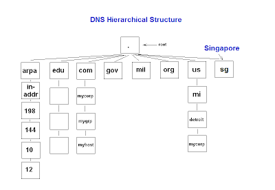
Do note that zone signing is only required for authoritative DNS servers. Remember that the DNS cache poisoning attacks are mostly targeted at the local DNS server caches of your ISPs. These recursive resolvers do not need to be signed by the root zone, as they are mostly non-authoritative (i.e. contain no zones on their owns) and simply perform recursive lookup on your behalf. The DNS resolvers belonging to the ISPs just need to be pre-configured to trust the public keys of the trust anchors - much like the Web browsers on your desktops that are pre-configured to trust the public certs of Verisign & Thawte.

New DNS Extension
To facilitate DNSSEC validations, four new resource records (DNSKEY, RRSIG, NSEC and DS) are introduced to existing DNS structure. DNSKEY (DNS public key) contains the zone public key. RRSIG (Resource Record Signature) contains the digital signature of the DNS response. NSEC (Next Secure) can inform about the denial-of-existence records. For example, if the zone only contains record A and D but you ask for B, it would return "A NSEC D" indicating the non-existence of records B and C. Lastly, DS (Delegation Signer) is used to validate between the parent and child zones, which are both DNSSec enabled.

IPSec
In most situations, the clients would simply ask the local DNS servers to perform DNSSec validation on their behalf. For maximum protection, you may also want to setup IPSec communications between the clients and the local servers. In corporate environments, these computers may use their domain certs for such domain IPSec setup. Note that IPSec is optional for DNSSec.

Name Resolution Policy Table (NRPT)
What if you wish to reject DNS response from non-DNSSec enabled DNS servers or making IPSec connection compulsory? You can influence such behaviours by the means of Name Resolution Policy Table (NRPT). Before issuing any queries, the DNS client will consult the NRPT to determine if any additional flags must be set in the query. Upon receiving the response, the client will again consult the NRPT to determine any special processing or policy requirements. In Windows Server 2008 R2 implementation, the following NRPT properties may be set using Group Policy:

1) Namespace: Used to indicate the namespace to which the policy applies. When a query is issued, the DNS client will compare the name in the query to all of the namespaces in this column to find a match.

2) DNSSEC: Used to indicate whether the DNS client should check for DNSSEC validation in the response. Selecting this option will not force the DNS server to perform DNSSEC validation. That validation is triggered by the presence of a trust anchor for the zone the DNS server is querying. Setting this value to true prompts the DNS client to check for the presence of the Authenticated Data bit in the response from the DNS server if the response has been validated, If not, the DNS client will ignore the response.

3) DNS Over IPsec: Used to indicate whether IPsec must be used to protect DNS traffic for queries belonging to the namespace. Setting this value to true will cause the DNS client to set up an IPsec connection to the DNS server before issuing the DNS query.

4) IPsec Encryption Level: Used to indicate whether DNS connections over IPsec will use encryption. If DNSOverIPsec is off, this value is ignored.

5) IPsec CA: Refers to the CA (or list of CAs) that issued the DNS server certificates for DNSSec over IPsec connections. The DNS client checks for the server authorization based on the server certificates issued by this CA. If left un-configured, all root CAs in the client computer’s stores are checked. If DNSOverIPsec is off, this value is ignored.

Saturday, July 31, 2010

Part 1: Prologue to DNS Security Extensions (DNSSec)

The Root DNS has recently been digitally signed (~2 weeks ago) as announced on its root DNS webpage. In other words, the signed root zone with actual key (as a root trust anchor) is now ready and available for validated DNS queries and transfers, including its security-aware child zones.

Microsoft also recently published an updated 80+ page implementation guide of DNSSec on Windows server 2008 R2. Note that DNSSec is not Microsoft or any vendor proprietary standard but is ratified by IETF in RFCs 4033, 4034, and 4035.

But why DNSSec is important? Everyone understands that DNS is the yellow-pages of Internet. However, it is weakly implemented in terms of security standards, as it is vulnerable to spoofing attacks, in particular DNS cache poisoning. To highlight its importance, we need to first understand the inherent security weaknesses on traditional DNS.

For the sake of efficiency, chances are you will be relying on your local ISP DNS servers to resolve all DNS queries by your favourite web browsers and email clients. Depending on the DNS configuration, the local DNS servers may conduct recursive queries all the way from the Intenet root zone to the respective domain authoritative servers or simply forward the queries to its "nearby" peers. (I suspect most DNS servers are configured in the latter mode rather than the former.) The obtained records will usually be locally cached for the use of subsequent queries until the expiry of TTL (Time-To-Live)

During this chain of recursive lookup, the resolver just weakly verifies the authenticity of the response based on some matching parameters (i.e. XID value, ports, addresses, and query types) that are sent in plain. Parameters, such as ports (default UDP 53) and remote server address value, can be easily guessed. Only XID value may present some challenge, as it is randomised. However, the challenge is not insurmountable, as it is only 16-bit long.


This weakness may allow a malicious attackers to guess the right values and send spoofed DNS response to your ISP servers, hoping to alter the cached DNS records. The malicious user can also increase his odds of success by sending many spoofed UDP response packets, each with different XID values. The attacker can insert any DNS data of his choosing into the response for the queried name and type. For example, the malicious user can place the IP address of his own server in a spoofed response to a query for the Web site of a bank like dbs.com.sg or online merchant. In another possible MITM (man-in-the-middle) attack scenario, a malicious network engineer in some large ISPs may plant a rogue DNS server to intercept any DNS queries from the smaller downstream ISPs and return any values that he wants. Obviously, the results can be catastrophic.

In my next post, I will discuss about how DNSSec can provide authentication and integrity protection to circumvent these attacks.

Sunday, July 25, 2010

Internet Load Balancing for Dual WAN Links to ISP

Recently, the WAN upgrade to our ISP is complete with dual redundant paths. We were asked if we could allow our Internet surfing users utilizing both links as much as possible instead of leaving one link to be idle most of the time. At the same time, it must not break the existing path redundancy. Since BGP rules Internet routing, we are using it to our advantage.

Below is the simplified network diagram to keep this discussion simple. (Click to enlarge)


Our 2 routers and the provider's routers are peered in full mesh eBGP. We advertised our public IP subnet (say 160.1.1.0/29) to the world via the 2 ISP routers (i.e. ISP R1 and ISP R2). By default in BGP, only 1 best route (i.e. default route) from either ISP R1 or ISP R2 is chosen as the path to the Internet. To influence the routing behavior, AS path prepend is used to influence inbound traffic and local preference to outbound traffic. As for load-balancing, whatever traffic that entered via R1 will route through ISP R1 and the similar applies to R2. This is our strategy for ISP link load-balancing:
  1. We further break our public IP subnet into 2 halves i.e. 160.1.1.0/30 and 160.1.1.4/30 and advertise them via both R1 and R2.
  2. On R1, we prepend AS path on advertised route 160.1.1.4/30 to make it less desirable for inbound traffic to use this route via R1. On R2, we prepend AS path on route 160.1.1.0/30.
  3. On R1, higher local preference is set for default route (0.0.0.0/32) advertised from ISP R1. Hence, ISP R1 will be the preferred next-hop for all outbound Internet traffic entered via R1. As for R2, the next preferred next-hop will be ISP R2.
  4. In summary, the path will become R1 <-> ISP R1 and R2 <-> ISP R2. We influence inbound traffic by making the other route less attractive and outbound traffic by making the route more attractive. If either R1 or R2 link were down, the remaining active link will take over all the traffic.

As for load-balancing between our routers (R1 & R2), it is more straightforward. Have both routers to advertise default route (on same metric) into the IGP (e.g. OSPF or RIP) by using "default information-orginate" router command. Alternatively, you may prefer GLBP (Gateway Load Balancing Protocol) for multiple clients.

The diagram (courtesy from my colleague MT) below illustrates the BGP load-balancing concept described above. (Click to enlarge)


Any sample configuration? Here you are:

On R1:
router bgp 65001
bgp router-id 172.16.1.1
bgp log-neighbor-changes
no auto-summary
neighbor 172.16.1.3 remote-as 65002
neighbor 172.16.1.3 route-map R1-ISPR1-MAP out # apply AS path prepend
neighbor 172.16.1.3 activate
neighbor 172.16.1.4 remote-as 65002
neighbor 172.16.1.4 route-map ISPR1-R1-MAP in # set higher local preference
neighbor 172.16.1.4 activate
no synchronization
network 160.1.1.0 mask 255.255.255.252 # route advertisement
network 160.1.1.4 mask 255.255.255.252
!
# exact routes must exist before they can be advertised in eBGP!
# since we are using NAT, just create some "phantom" routes
ip route 160.1.1.0 255.255.255.252 null0
ip route 160.1.1.4 255.255.255.252 null0
!
!
# Use NAT overload for internal users accessing Internet
ip nat pool INET_POOL 160.1.1.1 160.1.1.1 netmask 255.255.255.252
ip nat inside source list INSIDE_VLAN pool INET_POOL overload
!
ip access-list standard INSIDE_VLAN
permit 192.168.2.0 0.0.0.63
!
access-list 11 permit 160.1.1.0 0.0.0.3
access-list 12 permit 160.1.1.4 0.0.0.3
!
#make certain route advertised by this router less desirable
#to influence inbound traffic
route-map R1-ISPR1-MAP permit 10
match ip address 12
set as-path prepend 65001 65001 65001
!
route-map R1-ISP1-MAP permit 20
match ip address 11
!
#prefer default route from specific ISP router to influence outbound traffic
route-map ISPR1-R1-MAP permit 10
set local-preference 200

On R2:
router bgp 65001
bgp router-id 172.16.1.2
bgp log-neighbor-changes
no auto-summary
neighbor 172.16.1.3 remote-as 65002
neighbor 172.16.1.3 route-map ISPR2-R2-MAP in
neighbor 172.16.1.3 activate
neighbor 172.16.1.4 remote-as 65002
neighbor 172.16.1.4 route-map R2-ISPR2-MAP out
neighbor 172.16.1.4 activate
no synchronization
network 160.1.1.0 mask 255.255.255.252
network 160.1.1.4 mask 255.255.255.252
!
ip route 160.1.1.0 255.255.255.252 null0
ip route 160.1.1.4 255.255.255.252 null0
!
!
ip nat pool INET_POOL 160.1.1.5 160.1.1.5 netmask 255.255.255.252
ip nat inside source list INSIDE_VLAN pool INET_POOL overload
!
ip access-list standard INSIDE_VLAN
permit 192.168.2.0 0.0.0.63
!
access-list 11 permit 160.1.1.0 0.0.0.3
access-list 12 permit 160.1.1.4 0.0.0.3
!
route-map R2-ISPR2-MAP permit 10
match ip address 11
set as-path prepend 65001 65001 65001
!
route-map R2-ISP2-MAP permit 20
match ip address 12
!
route-map ISPR2-R2-MAP permit 10
set local-preference 200

Wednesday, July 21, 2010

First Experience with Dell PowerConnect Switches

We just brought in some new stackable Dell PowerConnect 6248 switches, which compete against the Cisco Catalyst 3750 series. The Dell switches cost slightly under half of what Cisco 3750 switches would normally cost.

I ran through the console and noticed that the CLI was unwittingly similar to Cisco IOS. Most of the basic L2 and L3 switch commands (e.g. switchport, spanning tree, ip route etc) are there, except VRF-lite which I used it extensively to separate the different routing domains for management and security purposes.

Another noticeable difference is that Dell doesn't allow you to perform routing on the management vlan interface, which is defaulted to vlan 1. If you intend to route on vlan 1, you would need to create a new vlan & assign it as the management vlan.

1) Creating a new vlan

DellPowerConnect(config)#vlan database
DellPowerConnect(config-vlan)#vlan 4093
Warning: The use of large numbers of VLANs or interfaces may cause significant
delays in applying the configuration.
DellPowerConnect(config-vlan)#exit


2) Assign new management vlan

DellPowerConnect(config)#ip address ?

bootp Set the protocol to bootp.
dhcp Set the protocol to dhcp.
none Set the protocol to none.
vlan Configure the Management VLAN ID of the switch.
Specify an IP address in A.B.C.D format.
DellPowerConnect(config)#ip address vlan 4093

The default subnet for Management VLAN is 192.168.2.0/24. If it overlaps with your other VLANs, you would have to change the subnet as well.

Monday, June 14, 2010

IEEE 802.1AE (a.k.a MACSec)

IEEE 802.1AE Media Access Control Security (MACSec) aims to integrate security protection into wired Ethernet to secure LANs from attacks such as passive wiretapping, masquerading, man-in-the-middle and some denial-of-service attacks.

MACSec helps assure ongoing network operations by identifying unauthorized stations on a LAN and preventing communication from them. It protects control protocols that manage bridged network and other data through cryptography techniques that authenticate data origin, protect message integrity, and provide replay protection and confidentiality. By assuring that a frame comes from the station that claimed to send it, MACSec can mitigate attacks on Layer 2 protocols. The proposed standard safeguards communication between trusted components of the network infrastructure by providing hop-by-hop security. This distinguishes it from IPSec, which protects applications on an end-to-end basis. Network administrators make use of MACSec by configuring a set of network devices to use the protocol.

When a frame arrives at a MACSec station, the MACSec Security Entity (SecY) decrypts the frame if necessary and computes an integrity check value (ICV) on the frame and compares it with the ICV included in the frame. If they match, the station processes the frame as normal. If they do not match, the port handles the frame according to a preset policy, such as discarding it.

802.1AE provides encapsulation and the cryptography framework for Ethernet protection. It requires supporting protocols for key management, authentication and authorization. To meet this need, the IEEE is defining an additional standard, 802.1af MAC Key Security, an extension of 802.1X that manages short-lived session keys used to encode and decode messages. An initial key, or master key, is typically obtained by an external method such as 802.1X and IETF's Extensible Authentication Protocol. A third related protocol under development is 802.1AR, Secure Device Identity, which ensures the identity of the trusted network component.

Currently, Cisco incorporates MACSec as a security feature under the Cisco TrustSec Framework

Reference: http://www.networkworld.com/details/7593.html?def

More about Cisco TrustSec Architecture

Friday, June 4, 2010

Musical Fountain @ Las Vegas

I like this musical fountain, which is just in front of Bellagios Hotel where I stayed in Mar earlier this year.

Thursday, June 3, 2010

SID duplication

Recently, I added a couple of VMs (Windows 2008 Server R2) from the same image. I did sysprep on the original image and just duplicate the VHD thinking that the sysprep process would reset the original SID. Depending on which point that you capture the VHD image after sysprep (i.e. SID is fixed once the Win7 logo appears), all subsequent duplicate VHD may still share the same SID as the first duplicate. I didn't realise it until I failed to add the duplicate VMs to a same security group. Hence, it's always recommended to capture the image right after the sysprep shutdown, so that you can re-use the same image again and again. (Hint: always shut and do not reboot after sysprep, which SID will be fixed during the initial booting process). 

In case of suspected SID duplication, there is this wonderful "name2sid" to find out if there's duplicate SID on the domain. Download it and check it against other servers, as well as the domain e.g.

name2sid contoso.com
name2sid Host01
name2sid Host02 and so forth

And there is also this blog post that mentioned about how to build an unattended installation XML and automated sysprep on the latest W2K8 R2 and Win7 images.

Wednesday, April 21, 2010

How to add device for SNMP Trap Monitoring in Nagios

SNMP Trap is pretty like syslog. It sends error messages to the Network Management System(NMS) like Nagios. Nagios doesn’t support SNMP trap by default. There is a Nagios plugin called SNMPTT that translate the received SNMP trap to the Nagios console. To install SNMPTT on Nagios, I used this guide "How to recieve SNMP Trap in Nagios". Afterwhich, you may follow the steps below to load additional SNMP MIBS trap for each managed device.

1) Load and compile MIBS to Nagios
This is the command to compile MIBS to Nagios server:
snmpttconvertmib --in= --out=/etc/snmp/snmptt.conf. --exec='/usr/local/nagios/libexec/eventhandlers/submit_check_result $r TRAP 1'

It would be tedious if there are too many MIBs files. Therefore, I wrote a simple bash script called “loadMIBS to compile all the MIBS in a folder.
if [ $# -ne 2 ]; then
echo "loadMIBS 'folder' 'device'"
exit 1
fi
for file in $( ls $1 ); do
/usr/sbin/snmpttconvertmib --in=$1\/$file \
--out=/etc/snmp/snmptt.conf.$2 \
--exec='/usr/local/nagios/libexec/eventhandlers/submit_check_result $r TRAP 1'
echo "MIBS loaded in /etc/snmp/snmptt.conf.$2"
done

2) Inform SNMPTT on the newly compiled Files
Modify /etc/snmp/snmptt.ini to include the earlier files:

[TrapFiles]
snmptt_conf_files =
/etc/snmp/snmptt.conf.devicename1
/etc/snmp/snmptt.conf.devicename2

END

3) Add the new Device to Nagios configuration file
I have created a standard file to consolidate all SNMP Trap devices at /usr/local/nagios/etc/objects/snmptrap.cfg. Just follow the example below:

define host{
use windows-server ; Inherit default values from a template
host_name HostA
alias HostA

address xx.xx.xx.xx ; IP address of the host
}

define host{
use windows-server ; Inherit default values from a template
host_name HostB
alias HostB
address xx.xx.xx.xx ; IP address of the host
}

define hostgroup{
hostgroup_name snmp_group ; The name of the hostgroup
alias SNMP TRAP
members HostA, HostB
}

define service{
hostgroup_name snmp_group
use snmptrap-service
contact_groups netadmin ; Who to alert & contact
}

4) Define New TRAP service on Nagios
Separately, on the templates.cfg, I have added this SNMP trap service
# define snmp trap service for network
define service{
use generic-service
name snmptrap-service
check_command check-host-alive
service_description TRAP
passive_checks_enabled 1
register 0
is_volatile 1
check_period none
max_check_attempts 1
normal_check_interval 1
retry_check_interval 1
notification_interval 31536000
notification_options w
}

Red: Make sure that the service description must match the submit_check_result parameter i.e. TRAP in this case. Otherwise, Nagios won't be able to match the recieved snmp trap to the passive service.

5) Verifying New SNMP Trap Service

Restart Nagios service and generate a test snmp trap from your managed device. If you do not receive an alert (email and/or sms), do the following:
  • Check that the snmp trap daemon is running i.e. ps -e | grep trap
  • Check the snmptt log that the trap is received
  • Click on the "Event Logs" of Nagios admin console. Check that the event handler "submit_check_result" is executed correctly.

Saturday, April 17, 2010

Redirect network traffic (ICMP redirect)

In some legacy ethernet LANs, you may encounter a flat network with a huge subnet with hundreds or even thousands of PCs on it. As network grows in complexity, more gateways are added to link this LAN to more external networks. For most PCs, you would expect that only default route exists on them. How do the PCs able to send traffics to external networks without adding static routes on them? This is a classic example from Cisco, which used ICMP redirect.

For example, the two routers R1 and R2 are connected to the same Ethernet segment as Host H. The default gateway for Host H is configured to use router R1. Host H sends a packet to router R1 to reach the destination on Remote Branch office Host 10.1.1.1. Router R1, after it consults its routing table, finds that the next-hop to reach Host 10.1.1.1 is router R2. Now router R1 must forward the packet out the same Ethernet interface on which it was received. Router R1 forwards the packet to router R2 and also sends an ICMP redirect message to Host H. This informs the host that the best route to reach Host 10.1.1.1 is by way of router R2. Host H then forwards all the subsequent packets destined for Host 10.1.1.1 to router R2.


ICMP redirect is enabled on most Cisco routers by default. However, it is disabled by Cisco security devices (e.g. PIX/ASA) by default. To permit same interface redirect or icmp redirect, issue this command: same-security-traffic permit inter-interface

Friday, April 2, 2010

Failover Clustering with StarWind iSCSI

Recently, I attended a well-known iSCSI SAN vendor seminar. The product is good and it provides all kind of storage virtualization (except deduplication), including replication, thin provisioning etc. The main selling point is the frameless architecture that is scalable and you can manage the whole lots of their SAN boxes as one virtual instance. The main drawback is pricing and it can't inter-operate with other storage solutions. Hence, there is a potential vendor lock-in.

I recalled some MVP speaker in Las Vegas introduced a software iSCSI target called "StarWind iSCSI". I decided to give it a try and set it up at my home network. The setup looks like this:


To prevent single box failure, I mirrored 2 virtual volumes across both StarWind servers (which are now iSCSI SAN boxes. Joining them to domain would make administration even easier). Creating the virtual HA volumes and exporting them as iSCSI targets is easy with StarWind with this step-by-step guide from the vendor.

Next, I setup 2-node failover cluster and both nodes are able to connect to the iSCSI targets with MPIO. I added file service to the cluster with a large musical video file that I captured in Las Vegas. I mapped a drive from the client PC on the public net and start playing it. During the play, I purposely shut down StarWind1 server (which is the source target). The video paused a few seconds before the partner (StarWind2) took over. I'm impressed.

Thursday, April 1, 2010

Storage Virtualization

As we are implementing Microsoft virtualization, more and more storage space are being used up rapidly. Another issue is storage availability. As we cluster up more VM hosts, major single points of failure still remain on the shared cluster storage. Even if storage can be fully replicated within a single site, any site-wide disaster (like flood, fire etc) can wipe off any data shortly. This is where storage virtualization comes into the picture. Wiki defines storage virtualization as the abstraction (separation) of logical storage from physical storage.

Let's take a look at the jargon used and how they can help solve the above issues, mainly on over-provisioning (that lead to high costs) & availability/DR related issues.
  • RAID: Some said RAID is the earliest form of storage virtualization, as a logical volume can span across multiple disks to prevent single disk failure.
  • I/O Multipathing (MPIO): In the event that one or more of these components fails, causing the path to fail, multipathing logic uses an alternate path for I/O so that the servers & applications can still access their data.
  • Remote synchronization: To eliminate storage as single point of failure, data across two separately located storage are replicated over the network on a per volume basis. It presents a single logical volume to the servers, although it may span across different storage boxes. It is also essential to implement multi-site failover clustering for Windows 2008 servers.
  • Thin provisioning: It is easier and less troublesome to extend a volume rather than shrinking it. Hence, most administrators tend to over-provision storage space for applications. To reduce wastage, thin provisioning allows administrators to provision a large volume but only a small fraction is actually allocated until the applications occupy more space over time.
  • Thin replication: You replicate a "thinly" provisioned volume. Only delta changes will be replicated across and save network bandwidth.
  • Point in time Snapshot: To simplify data restoration & DR recovery, periodic snapshots on the storage are taken over time. It allows you to rollback data to certain points in time.
  • Deduplication: When you implement server virtualization or VDI, most of the bits and bytes of the VHDs are identical. Deduplication further optimizes storage space by removing duplicated bits & bytes.

Wednesday, March 31, 2010

Multiple Path I/O (MPIO) for iSCSI storage

To ensure server to storage path continuity, we usually deploy redundant physical path components, including NICs (for iSCSI) and HBAs (for FC, SCSI etc). In the event that one or more of these components fails, causing the path to fail, multipathing logic uses an alternate path for I/O so that the servers and applications can still access their data.

Each storage vendor may introduce their own Device Specific Module(DSM) solution, such as PowerPath for EMC. If you did not cater for budget to purchase specific vendor MPIO module, Microsoft did introduce a generic DSM free. I tried it on my W2K8 R2 server on Hyper-V VM and Dell-EMC AX4-5i storage using Round Robin to load balance among the four iSCSI paths. If you are also using W2K8, install MPIO as a feature using Server Manager or "Add-WindowsFeature" cmdlet in Server Core.


Click on Administrative Tools -> MPIO and check on "Add Support for iSCSI devices" on the "Discover Multi-Paths" tab. Reboot the server. On Server Core, you may run 
>"mpclaim -r -i -d "MSFT2005iSCSIBusType_0x9""


Invoke iSCSI initiator and connect to the iSCSI targets - make sure that the option "Enable multi-path" is checked. On server core, you may invoke the same initiator using "iscsicpl.exe" command.


Click "Advanced", connect using different path each time. Repeat and rinse for the number of different paths that you have. Click on "Devices" -> "MPIO". And you should the load balancing policy and the multiple paths linking to the Disk devices.


 For a more complete Server Core configuration, see "MPIO with Windows 2008 R2 Server Core and iSCSI".

Monday, March 29, 2010

Storage options for Hyper-V

Found this excellent online resource that discuss various storage options for Hyper-V. This table is particularly useful:

Sunday, March 28, 2010

Missing Deployed Printer Node in Windows 2008 GPMC

Windows Server 2003 R2 onwards supports "Printer Deployment with GPO". There is an excellent guide on WindowsNetworking.com that illustrates the step-by-step deployment.

However, if you attempt the same step in W2K8, you will realize a missing "Deployed Printer Node" in the GPO editor. To get it back, add the "RSAT - Print & Document Services Tool" using "Add Features" in the Server Manager as below:


Go back to GPO editor, expand "Computer or User Configuration" (depending whether per-computer or per-user deployment basis), Policies, and Windows Settings as below:

Live Migration on Multi-Site Clustering POC

Earlier in my post, I mentioned about the "Cheapskate Multi-site Cluster for Hyper-V R2 HA". I did a simple POC using low cost host-based replication called "SteelEye Data Keeper" (as compared to SAN replication) to provide asynchronous data replication over the network.

This is my 2-node cluster POC setup using MS Failover Clustering with quorum type "Node and File Share Majority". In this setup, we can afford any one (not two) site failure to provide continuity.


In this Hyper-V cluster, I have a few VMs running on both clusters. Let's do a live migration of one of the VMs called "PrintSrv" from Cluster01 to Cluster 02.


During migration, I continue my RDP session on PrintSrv to ensure that the VM is still up & running while in migration.


After a while, the current node owner is Cluster02. Live migration is complete without any down time.

Thursday, March 25, 2010

Failover Clustering Error 80070005

When I run Validation of my test failover clustering on Hyper-V, I get the following error report:


Validate Cluster Network Configuration Validate the cluster networks that would be created for these servers. An error occurred while executing the test. There was an error initializing the network tests. There was an error creating the server side agent (CPrepSrv). Creating an instance of the COM component with CLSID {E1568352-586D-43E4-933F-8E6DC4DE317A} from the IClassFactory failed due to the following error: 80070005.

This was despite the fact that I checked through all network connection & properties. I even made sure that the network binding order were correct on both nodes - the Public network card is at the top, above the Private network card.

This error usually comes when you have cloned VM. To check whether you have duplicate SID on the cloned VM, check out this blog post. To resolve it, sysprep the cloned VM (thanks to Farseeker) and the problem should go away.

According to this post, another smaller possible reason is that your environment is completely Windows 2008 Domain Controller (note: this error still persist even if the forest/domain level is at W2K3)). To resolve this error

1) Login to your domain controller using domain admin rights

2) Click on start -> run> dcomcnfg

3) Expand Component services -> Computers and right click on My Computer and click on properties

4) Go to Default Properties tab

5) Under default impersonation level select impersonate and apply it.

6) reboot your Domain controller and then try validation again.

Note: if your validation still fails. Dis-join machines from domain and rejoin and try again.

Monday, March 22, 2010

Cheapskate Multi-site Cluster for Hyper-V R2 HA

MS W2K8 R2 announces 2 important new HA features for virtualization: (1) new cluster shared volume (CSV) for Hyper-V HA cluster & live migration and (2) multi-site clustering.

Hyper-V R2 cluster support VM HA & live migration using the Cluster Shared Volume (CSV). CSV is still a shared volume between 2 nodes, except that 2 nodes can own the volume concurrently (instead of single node ownership previously). You may have a single large CSV that stores multiple VHDs and load balance the VMs within the cluster. However, the common shared CSV is still the major single point of site failure (imagine a total site outage e.g. earthquake, power, flood etc).

On the other hand, multi-site clustering can solve the above site disaster issue - each server node owns its storage on one site & replication occurs between the differently located storage box. One site is defined as source storage and the other as target storage. It presents a single virtual volume to a pair of cluster. However, CSV does not support replicated volumes. Hence, only node may own this virtual LUN at any one time. Two types of replication exist - host-based and storage-based. Multi-site clustering supports Hyper-V R2. The recommended quorum type for this setup is "Node and File-share (instead of disk) majority" whereby the file share server also carry a vote. For better resiliency, the file share server is recommended to be hosted at the third site.

I found this online demo that used host-based replication solution - a software called "SteelEye Data Keeper Cluster". As compared to expensive SAN replication solution, an advantage of this software is the retrofitting of any existing storage, as it allows mirroring across different storage types & volume e.g. iSCSI to NAS, DAS to iSCSI etc.

Friday, March 19, 2010

Presentation Virtualization is back in Las Vegas

I thought the term "Presentation Virtualization" was dropped since launch of Windows Server 2008 R2, since it was hardly mentioned in any new Microsoft Windows 2008 R2 literature. It was almost used in synonymous with Remote Desktop Services (f.k.s Terminal Services) RemoteApp.

Right now, I'm attending the Virtualization Pro summit 2010 at Las Vegas. Presentation Virtualization is still mentioned by a few MVP speakers, including Sean Deuby. Sean defined Presentation Virtualization as the display being abstracted from the originating processes.

Friday, March 12, 2010

Delete Volume Group in Openfiler

Openfiler is a free open-source iSCSI solution, which I mentioned earlier. I've been trying to delete a Volume Group (VG) via the Brower GUI on Openfiler. The VG still remains.

I search the Internet and found this blog on how to remove the VG using CLI instead.

Step 1: Disable VG
vgchange –a n

Step 2: Remove VG
vgremove

Thursday, March 11, 2010

How I assign storage to a VM

Someone asked how I typically assign storage to a VM. This is what I usually did - separate the data from the binaries to minimize the chance of corruption in the event of outage.

C: System OS drive. Typically assign ~60GB fixed sized VHD.

D: is application drive where I would install the application binary in VHD. Size varies on application requirements.

E: is the data or log drive where I would store the system & application data & logs. If syslog or ftp is the application, expect a big storage space. Typically, I would assign direct SAN LUN with RAID (e.g. iSCSI) to this volume. I would also redirect the host Firewall/IIS logs here for audit purposes.

In summary, C & D drives are typically assigned with VHDs that are stored on the host's direct or SAN storage while I would assign direct LUN with redundant RAID to E drive. The rationale is that the system & application binaries in C & D can be easily restored by installation but not the logs/data on E drive. Always remember to keep data and binaries separate.

Wednesday, March 10, 2010

Don't VM your PDC emulator

I learnt a mistake by virtualizing my Primary Domain Controller (PDC) emulator, which is the default master NTP clock on the Windows domain. PDC emulator is one for the five essential FSMO roles in maintaining the Microsoft Active Directory. Despite its misleading name PDC emulator for NT4.0, it is still used to support several AD operations, including being the default master NTP clock, password replication & DFS namespace meta data within the domain.

To find out which DC is the PDC emulator, run this on any DC: netdom query fsmo

The virtualized PDC seems to always "trust" Hyper-V time synchronization (part of Hyper-V integration service) more than the external NTP server (a Linux box), which I manually configured using w32tm (see this). Although the time was in-sync within the domain, it was out-of-sync with the real world.

Frustrated, I have to set aside a R200 1-U DELL server, run "dcpromo" and take over the PDC role. Finally, the clock is in sync. To sync the rest of domain controllers on VM, you've got to shutdown the VMs, turn off the time synchronization service on the Hyper-V integration setting and boot them up one-by-one.

KMS requirements

Microsoft Volume Licensing Activation comes in 2 forms: Multiple Activation Key (MAK) and Key Management Service (KMS). It is also well published in Microsoft website if you have at least 5 servers or 25 clients, you should go for KMS.

Now, we have about a dozen of servers in a particular network activated by KMS. Recently, I joined the first Win7 client to the domain and was unable to activate this client. Error: "The count reported by your KMS server is insufficient". Ops! I thought I already have more than 5 servers in this domain!?

A further check with Microsoft now confirms this:
KMS volume activation requires a minimum number of physical Windows clients: five (5) for Windows Server 2008, or twenty five(25) for Windows Vista. However, KMS does not differentiate between the two systems when counting the total number of clients. For example, a KMS host with a count of three (3) Windows Vista clients and two (2) Windows Server 2008 clients would activate the two (2) Windows Server 2008 clients because the cumulative count is five (5) clients. But KMS would not activate the three (3) Windows Vista computers until the total client count reached twenty-five (25). Each time a new machine contacts a KMSHOST, it is added to the count for thirty calendar (30) days, after which its record is deleted, similar to Time-To-Live (TTL) for Domain Name System (DNS) records.

Monday, March 8, 2010

Cisco Flexible Netflow

Cisco NetFlow is a IP traffic monitoring protocol used in Cisco IOS devices - mainly used for bandwidth monitoring and other reporting purposes, such as billings. A simple netflow configuration may look like this

1) To create flow export to a server:
ip flow-export destination {hostname|ip_address} {port no.}

2) Apply on interface:
interface {interface} {interface_number}
ip route-cache flow

As you can see, almost every traffic will be exported out. What if you want to monitor only a specific flow? Cisco now introduces Flexible Netflow, which export v9 and v5 (from Cisco 12.4(22)T). A simple configuration may now look like this:

(define the specific flow that you are interested in)
flow record app-traffic-analysis
description This flow record tracks TCP application usage
match transport tcp destination-port
match transport tcp source-port
match ipv4 destination address
match ipv4 source address
collect counter bytes
collect counter packets

(export to a netflow analyzer)
flow exporter export-to-server
destination 172.16.1.1
flow monitor my-flow-monitor
record app-traffic-analysis
exporter export-to-server

(apply on an interface)
interface Ethernet 1/0
ip flow monitor my-flow-monitor input

Of course, you would also need netflow analyzer software to process these collected data. There are several on the Internet that you can try out, including this free version ManageEngine Netflow Analyzer that supports up to 2 interfaces.

References:
  1. Getting Started with Configuring Cisco IOS Flexible NetFlow
  2. Cisco IOS Flexible NetFlow Technology Q&A

Saturday, March 6, 2010

Hello Remote Desktop Services, Goodbye Terminal Services

With the major launch of Microsoft Windows 2008 R2, Terminal Services is now renamed as Remote Desktop Services (RDS) to indicate additional functionality. The major addition is the support of Virtual Desktop Infrastructure (VDI).

Terminal Server is now renamed as Session Host. Session Broker (in-built load-balancer) is now renamed Connection Broker. Presentation Virtualization (Present-V) has apparently been taken out of Microsoft dictionary - RDS RemoteApp is used in place. The term (Present-V) which you saw in my earlier posts can now be replaced with RDS RemoteApp instead.

Securing enterprise applications using RDS RemoteApp

Windows 2008 has a new feature in Remote Desktop Services (RDS a.k.a Terminal Services) that allows individual applications to be presented to users via RDP. Although the applications are installed and run on Terminal Server (now known as Session Host), Users interact with the virtualised applications as if they were installed locally. This feature is known as RemoteApp.

There's a growing security demand for Internet traffic to be segregated from the corporate applications due to the recent high profile APT incidents. We conducted a trial that leveraged primarily on this RDS RemoteApp. Internet applications (i.e. Internet Explorer etc) are virtualised and executed via RDP, which effectively permit only screenshots, key stroke and mouse clicks to be transmitted between client and server. Even if the Internet applications were subverted by Trojans, it would have no impacts on existing corporate applications. Corporate applications are protected and there's no drop in user experiences. The setup is simple and fits well on existing infrastructure. And the trial is a huge success.

Tuesday, March 2, 2010

Zero Downtime Firmware Upgrade for Cisco ASA Active/Standby

We have a pair of Cisco ASA 5520 configured in Active/Standby mode. Both management interfaces share the same IP address. But, how do you upgrade both firmwares with zero down-time remotely? (Note: Both nodes may sync their configuration and state but not the ASA image).

SSH to the active node. Upgrade its image by doing "copy tftp: flash:" and configure the system to boot from new image "boot system image". Force the standby unit to take over by executing "failover exec standby failover active". The first part "failover exec standby" is to send command to the standby unit. "failover active" is to force the unit to takeover the active role. The connection will drop. Once you reconnect, you will be connecting to the other node. Repeat the same process on this newly active node mentioned in the first sentence of this paragraph. You may reload the standby unit for the new firmware to take effect by executing "failover reload-standby" from the active node when the upgrade is complete.